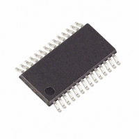
MAX9540EUI+ Maxim Integrated Products, MAX9540EUI+ Datasheet

MAX9540EUI+
Specifications of MAX9540EUI+
Related parts for MAX9540EUI+
MAX9540EUI+ Summary of contents
Page 1
... RGB to 5-Wire RGBHV Interface o Supports VGA-to-UXGA Resolution o Low Offset Voltage (±1mV) o 180MHz Large-Signal Bandwidth PART MAX9539EUI+* MAX9539EUI MAX9540EUI+* MAX9540EUI Note: All devices are specified over the -40°C to +85°C oper- ating temperature range. + Denotes lead-free package. * Future product—contact factory for availability. Applications Pin Configurations appear at end of data sheet ...
Page 2
Graphics Video Sync Adder/Extractor ABSOLUTE MAXIMUM RATINGS V to GND ..............................................................-0. GND...............................................................-6V to +0.3V EE IN_R, IN_G, IN_B, REST_R, REST_G, REST_B….....................................(V EE OUT_R, OUT_G, OUT_B Short Circuit to GND (Note 1) .....................................................Continuous OUT_R, OUT_G, OUT_B ...
Page 3
Graphics Video Sync Adder/Extractor MAX9539 DC ELECTRICAL CHARACTERISTICS (continued +5V -5V, GND = 0V +25°C.) (Notes 2 and 3) PARAMETER HSYNC, VSYNC INPUTS High Input Voltage Low Input Voltage High Input Current ...
Page 4
Graphics Video Sync Adder/Extractor MAX9540 DC ELECTRICAL CHARACTERISTICS (V = +5V -5V, GND = 0V +25°C.) (Notes 2 and 3) PARAMETER Supply Voltage Range Quiescent Supply Current Input Voltage Range ΔV DC-Restore Input Voltage ...
Page 5
Graphics Video Sync Adder/Extractor MAX9540 AC ELECTRICAL CHARACTERISTICS (V = +5V -5V, GND = 0V +25°C.) PARAMETER SYMBOL Large-Signal Bandwidth Slew Rate Channel-to-Channel Crosstalk Settling Time Input Voltage-Noise Density Input Current-Noise Density Sync Timing ...
Page 6
Graphics Video Sync Adder/Extractor (T = +25° +5V -5V, GND = 0V LARGE-SIGNAL GAIN FLATNESS vs. FREQUENCY (MAX9540) 0.3 IN_ = 1V P-P 0 +2V 0.1 0 -0.1 ...
Page 7
Graphics Video Sync Adder/Extractor PIN NAME 1 IN_R Red Video Input GND Ground 3 REST_R Red DC Restore. Connect a 1nF capacitor from REST_R to GND 10, 14, 15, 20, 21, N.C. No Connection. Not ...
Page 8
Graphics Video Sync Adder/Extractor PIN NAME 1 IN_R Red Video Input with Horizontal Sync GND Ground 3 REST_R Red DC Restore. Connect a 1nF capacitor from REST_R to GND 10, 14, N.C. No Connection. Not ...
Page 9
Graphics Video Sync Adder/Extractor obtained from the red input, vertical sync is obtained from the blue input, and composite sync is obtained from the green input. Like the MAX9539, the DC-restore func- tion removes any DC offset in the RGB ...
Page 10
Graphics Video Sync Adder/Extractor VIDEO INPUT (IN_) HOR. SYNC (HSYNC) VER. SYNC (VSYNC) RED OUTPUT (OUT_R) BLUE OUTPUT (OUT_B) GREEN OUTPUT (OUT_G) Figure 2. MAX9539 Input and Output Functionality VIDEO WITH SYNC (IN_) VIDEO OUTPUT (OUT_R/B/G) SYNC OUTPUT (_SYNC) Figure ...
Page 11
Graphics Video Sync Adder/Extractor * OPTIONAL BULK CAPACITANCE 0.1μF MAX9539 1 IN_R 3 REST_R 1nF 6 IN_G REST_G 8 1nF 11 IN_B 13 REST_B 1nF VSYNC 16 H/V SYNC LOGIC HSYNC SP_V SP_H 0.1μF ______________________________________________________________________________________ Functional Diagrams ...
Page 12
Graphics Video Sync Adder/Extractor * OPTIONAL BULK CAPACITANCE IN_R 1 REST_R 3 1nF IN_G 6 REST_G 8 1nF 11 IN_B REST_B 13 1nF 17 SP_V SP_C 22 SP_H ______________________________________________________________________________________ Functional Diagrams (continued) +5V 10μF* ...
Page 13
Graphics Video Sync Adder/Extractor BLADE 1 R 75Ω +700mV 0V -1. 75Ω 75Ω ______________________________________________________________________________________ Typical Application Diagram BACKPLANE H 75Ω 75Ω MAX9539 MAX4027 BLADE 2 MAX4027 75Ω MAX9540 MANAGEMENT ...
Page 14
Graphics Video Sync Adder/Extractor TOP VIEW IN_R 1 GND 2 REST_R 3 MAX9539 N.C. 4 I.C. 5 IN_G 6 GND 7 REST_G 8 N.C. 9 N.C. 10 IN_B 11 GND 12 REST_B 13 N.C. 14 TSSOP 14 ______________________________________________________________________________________ TOP VIEW ...
Page 15
... Maxim cannot assume responsibility for use of any circuitry other than circuitry entirely embodied in a Maxim product. No circuit patent licenses are implied. Maxim reserves the right to change the circuitry and specifications without notice at any time. Maxim Integrated Products, 120 San Gabriel Drive, Sunnyvale, CA 94086 408-737-7600 ____________________ 15 © 2007 Maxim Integrated Products ...


