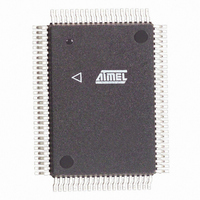
U2739M-BFT Atmel, U2739M-BFT Datasheet - Page 25

U2739M-BFT
Manufacturer Part Number
U2739M-BFT
Description
IC DECODER 1CHAN/SOURCE 100-PQFP
Manufacturer
Atmel
Type
Decoderr
Datasheet
1.U2739M-BFT.pdf
(69 pages)
Specifications of U2739M-BFT
Applications
Processing, IF Modules
Mounting Type
Surface Mount
Package / Case
100-MQFP, 100-PQFP
Lead Free Status / RoHS Status
Contains lead / RoHS non-compliant
Available stocks
Company
Part Number
Manufacturer
Quantity
Price
6.8.6
The SP-DIF format is frame based, which means one
frame represents one audio sampling period. Every frame
comprises 2 subframes a 32 bit referring to the left and
right sample. The data is transmitted in bi-phase coded
format. The frame synchronization pattern are based on
biphase violations and indicate whether a left or right
subframe follows.
The last 4 bi-phase coded bits of each subframe represent
the V (validity flag), U (user channel data), C (channel
status data) and P (parity) information as described in the
SP-DIF specification.
6.8.8
SPDIF
6.9
6.9.1
6.9.2
The RDI interface is designed according to the ‘Digital
Audio Broadcasting System: Specification of the
Receiver
Broadcasting System: Specification of the Receiver Data
Interface (RDI), Issue 1.4]. The RDI frames are
embedded into the IEC 958 interface. The RDI output
6.9.3
Rev. A1, 22-May-01
QFP144 QFP100
64
85
86
RDI Interface
RDI_TX/RX
SP-DIF Interface Description
SP-DIF Interface Timing Diagram
RDI Interface Signal Description
RDI Interface Description
RDI Interface Timing Diagram
Data
46
60
61
Frame sync. pattern
Interface
S3
C_DATA5/RDI_VBIT
RDI_RX
RDI_TX
S2
S1
Pin Name
(RDI)’
tH
tL
Figure 14. SP-DIF interface timing diagram
[Digital
Figure 15. RDI interface timing diagram
8 Zero’s (bi–phase coded)
2 * tH
SP–DIF subframe (left or right audio sample)
C–bus data bit 5 (pull down)
RDI receive data
RDI transmit data
Audio
Signal Description
2 * tL
Complete frames (left and right sample according to
64
audio sampling rate (48 resp. 24 kHz).
6.8.7
The SP-DIF interface was designed according the digital
audio interface IEC958 specification [CEI/ISO 958
Digital Audio Interface Standard].
data is provided in the extended format of the high
capacity mode. Further the RDI Control Channel (RCC)
can be implemented according to the preliminary specifi-
cation [Digital Audio Broadcasting System: Preliminary
Specification of the RDI Control Channel], [Proposal of
DAB Command Set for Receiver (DCSR)].
2 bit due to bi-phase coding) are transmitted at the
A0
Audio data bits (bi–phase coded)
SP-DIF Interface Timing
Parameter
3 * tH
A1
A2
PRD04TZ
PDIZ
PRO04T
Pad Type
A14
U2739M-B
A15
3 * tL
Flag bits (bi–phase coded)
V
inout
Dir.
out
U
in
C
5 V Tol.
25 (69)
P
x
x


