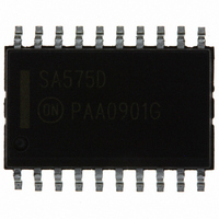
SA575DG ON Semiconductor, SA575DG Datasheet - Page 4

SA575DG
Manufacturer Part Number
SA575DG
Description
IC COMPANDOR 2CHAN GAIN 20-SOIC
Manufacturer
ON Semiconductor
Type
Compandorr
Datasheet
1.SA575DTBR2.pdf
(16 pages)
Specifications of SA575DG
Applications
Cellular Radio, Mixers
Mounting Type
Surface Mount
Package / Case
20-SOIC (7.5mm Width)
Package
20SOIC W
Operating Temperature
-40 to 85 °C
Product
General Purpose Audio Amplifiers
Output Type
Programmable Analog
Available Set Gain
+/- 1.5 dB
Common Mode Rejection Ratio (min)
80 dB
Thd Plus Noise
0.12 %
Operating Supply Voltage
5 V
Supply Current
4.2 mA
Maximum Power Dissipation
1116 mW
Maximum Operating Temperature
+ 85 C
Mounting Style
SMD/SMT
Audio Load Resistance
600 Ohms
Input Bias Current (max)
+/- 1 uA
Input Offset Voltage
3 mV
Minimum Operating Temperature
- 40 C
Supply Voltage (max)
7 V
Supply Voltage (min)
3 V
Lead Free Status / RoHS Status
Lead free / RoHS Compliant
Other names
SA575DG
SA575DGOS
SA575DGOS
Available stocks
Company
Part Number
Manufacturer
Quantity
Price
Company:
Part Number:
SA575DG
Manufacturer:
PANASONIC
Quantity:
201
Part Number:
SA575DG
Manufacturer:
ON/安森美
Quantity:
20 000
Functional Description
applications of the SA575 Compandor. More theory of
operation on compandors can be found in AND8159 and
AND8160. The typical applications of the SA575 low
voltage compandor in an Expandor (1:2), Compressor (2:1)
and Automatic Level Control (ALC) function are
explained. These three circuit configurations are shown in
Figures 2, 3, and 4 respectively.
system. The left channel, A, can be configured as a 1:2
Expandor while the right channel, B, can be configured as
either a 2:1 Compressor, a 1:2 Expandor or an ALC. Each
channel consists of the basic companding building blocks
of rectifier cell, variable gain cell, summing amplifier
and V
high performance uncommitted op amps which can be
utilized for application such as filtering, pre-emphasis/
de-emphasis or buffering.
applications demo board. Channel A is configured as an
expandor while channel B is configured so that it can be
used either as a compressor or as an ALC circuit. The
switch, S
ALC mode. Jumpers J
the additional op amps for signal conditioning or exclude
them from the signal path. Bread boarding space is
provided for R
the response can be tailored for each individual need. The
components as specified are suitable for the complete
audio spectrum from 20 Hz to 20 kHz.
non-inverting buffer where R
eliminated and R
C
inputs and outputs are AC coupled, these capacitors and
resistors can be eliminated. Capacitors C
setting the attack and release time constant.
8
This section describes the basic subsystems and
The SA575 has two channels for a complete companding
Figure 5 shows the complete schematic for the
The most common configuration is as a unity gain
, and C
REF
1
cell. In addition, the SA575 has two additional
12
, toggles the circuit between compressor and
are for DC blocking. In systems where the
1
, R
2
2
and R
, C
1
1
and J
, C
11
2
are shorted. Capacitors C
, R
2
1
, C
can be used to either include
10
, R
1
, C
11
2
, R
, C
10
10
, C
4
and C
and C
10
and C
11
9
are for
http://onsemi.com
so that
3
11
, C
are
5
,
SA575
4
circuit. The value of C
very low impedance to the lowest frequencies of interest.
Too small a capacitor will allow supply ripple to modulate
the audio path. The better filtered the power supply, the
smaller this capacitor can be. R
voltage to the amplifier of channel B. R
DC feedback path for the summing amp of channel B,
while C
are for power supply decoupling. C
eliminated if the power supply is well regulated with very
low noise and ripple.
Demonstrated Performance
frequency range of 20 Hz to 20 kHz with the component
values as shown in Figure 5 and V
expandor mode, the typical input dynamic range was from
-34 dB to +12 dB where 0 dB is equal to 100 mV
typical unity gain level measured at 0 dB @ 1.0 kHz input
was "0.5 dB and the typical tracking error was "0.1 dB
for input range of -30 to +10 dB.
was from -42 dB to "18 dB with a tracking error +0.1 dB
and the typical unity gain level was "0.5 dB.
from -42 dB to +8.0 dB with typical output deviation of
"0.2 dB about the nominal output of 0 dB. For input
greater than +9.0 dB in ALC configuration, the summing
amplifier sometimes exhibits high frequency oscillations.
There are several solutions to this problem. The first is to
lower the values of R
is to add a current limiting resistor in series with C12 at
Pin 13. The third is to add a compensating capacitor of
about 22 to 30 pF between the input and output of summing
amplifier (Pins 12 and 14). With any one of the above
recommendations, the typical ALC mode input range
increased to +18 dB yielding a dynamic range of over
60 dB.
C
The applications demo board was built and tested for a
In the compressor mode, the typical input dynamic range
In the ALC mode, the typical input dynamic range was
6
is for decoupling and stabilizing the voltage reference
7
is a short-circuit to ground for signals. C
6
6
and R
should be such that it will offer a
7
to 20 kW each. The second
12
provides DC reference
CC
6
14
and R
= 5.0 V. In the
can also be
7
14
provide a
RMS
and C
. The
15


