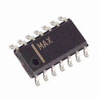
MAX4298ESD+T Maxim Integrated Products, MAX4298ESD+T Datasheet - Page 7

MAX4298ESD+T
Manufacturer Part Number
MAX4298ESD+T
Description
IC STEREO DVR AUDIO 14-SOIC
Manufacturer
Maxim Integrated Products
Type
PSRR Stereo Driverr
Datasheet
1.MAX4298ESDT.pdf
(14 pages)
Specifications of MAX4298ESD+T
Applications
Desktop Audio, MP3, USB
Mounting Type
Surface Mount
Package / Case
14-SOIC (3.9mm Width), 14-SOL
Lead Free Status / RoHS Status
Lead free / RoHS Compliant
The MAX4298/MAX4299 are audio system ICs de-
signed for single +5V applications. The MAX4299 has a
stereo headphone driver, a microphone amplifier, and
a 100mA +3.3V linear regulator; the MAX4298 has the
stereo headphone driver only. The MAX4298/MAX4299
are designed specifically for harsh digital environments
where board space is at a premium and the digital
MAX4298
10-PIN
MAX
10
—
—
—
—
—
—
—
1
2
3
4
5
6
7
8
9
Microphone Amp + 100mA Linear Regulator
14-PIN SO
MAX4298
1, 7, 8, 14
_______________________________________________________________________________________
10
11
12
13
—
—
—
—
—
—
2
3
4
5
6
9
Detailed Description
PIN
MAX4299
TSSOP
16-PIN
16
10
11
12
13
14
15
—
1
2
3
4
5
6
7
8
9
Ultra-High PSRR Stereo Drivers +
3, 12, 18, 19
20-PIN SO
MAX4299
10
11
13
14
15
16
17
20
1
2
4
5
6
7
8
9
C
MICOUT
REGON
NAME
PGND
MICIN
OUT1
MUTE
OUT2
BYPASS
SV
GND
BIAS
REG
N.C.
V
IN1
IN2
FB
CC
CC
power supply is noisy. The design uses innovative
design techniques to achieve ultra-high power-supply
rejection across the audio signal band while, at the
same time, delivering a high current rail-to-rail output
drive capability. These devices are designed to drive
highly capacitive loads that may be encountered when
driving long cables to a remote load such as
desktop/notebook headphones or speakers. They are
fully compliant to PC99 standards. Figure 1 is the
Regulator Output. Bypass REG to GND with a 10 F
capacitor.
Regulator Feedback. Internal resistors from this point
to REG and GND define the regulator output value.
Adjustments can be made to the output value by
adding resistors in the same place externally.
Driver Amplifier Output
Power Ground for Driver Outputs
Ground
Inverting Input for Driver Amplifier
Bias Point for Amplifiers. Bypass BIAS to GND with a
1 F capacitor.
Standby Power Supply. Connect to a standby +5V
supply that is always on, or bypass with 220 F and
connect a Schottky diode from V
V
Microphone Amplifier Output
Inverting Input for Microphone Amplifier
Mute Digital Input. Connect to GND for normal
operation. When MUTE is connected to V
and OUT2 are muted, REG stays on, and MICOUT
stays on.
Bypass to GND with a 1 F Capacitor
Inverting Input for Driver Amplifier
Driver Amplifier Output
Power Supply. Connect to +5V.
No Connection. Not internally connected.
Regulator Control. Connect to V
operation. Connect to GND to shut off the regulator.
CC
if clickless power-down is not essential.
FUNCTION
Pin Description
CC
CC
for normal
to SV
CC
CC
. Short to
, OUT1
7


