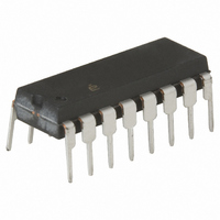
HA1-2556-9 Intersil, HA1-2556-9 Datasheet - Page 6

HA1-2556-9
Manufacturer Part Number
HA1-2556-9
Description
IC MULTIPLIER 4QUAD VOUT 16-DIP
Manufacturer
Intersil
Series
HAr
Datasheet
1.HA9P2556-9Z.pdf
(18 pages)
Specifications of HA1-2556-9
Function
Analog Multiplier
Number Of Bits/stages
4-Quadrant
Package / Case
16-CDIP (0.300", 7.62mm)
Lead Free Status / RoHS Status
Contains lead / RoHS non-compliant
Available stocks
Company
Part Number
Manufacturer
Quantity
Price
second order errors introduced by the dependence of V
collector current in the X and Y stages.
The purpose of the reference circuit is to provide a stable
current, used in setting the scale factor to 5V. This is
achieved with a bandgap reference circuit to produce a
temperature stable voltage of 1.2V which is forced across a
NiCr resistor. Slight adjustments to scale factor may be
possible by overriding the internal reference with the V
pin. The scale factor is used to maintain the output of the
multiplier within the normal operating range of ±5V when
full scale inputs are applied.
The Balance Concept
The open loop transfer for the HA-2556 is calculated using
Equation 2:
where;
An understanding of the transfer function can be gained by
assuming that the open loop gain, A, of the output amplifier
is infinite. With this assumption, any value of V
generated with an infinitesimally small value for the terms
within the brackets. Therefore we can write Equation 3:
which simplifies to Equation 4:
This form of the transfer equation provides a useful tool to
analyze multiplier application circuits and will be called the
Balance Concept.
Typical Applications
Let’s first examine the Balance Concept as it applies to the
standard multiplier configuration (Figure 2).
V
0 =
(
V
OUT
A
B
A = Output Amplifier Open Loop Gain
V
5V = Fixed Scaled Factor
X+
X,
(
---------------------------------------------------------------- - - V
V
-V
X+
= A
V
X-
Y,
-V
) x V
V
X-
(
------------------------------------------------------------------ - - V
V
V
V
V
Z
V
(
X
X
Y
Y
) x V
X+
-
5V
+
-
+
Y+
1/5V
= Differential Input Voltages
(
-V
-V
X-
Y+
+
+
-
-
FIGURE 2. MULTIPLIER
Y-
) x V
5V
-V
) = 5V V
Y-
(
Y
X
)
Y+
HA-2556
(
(
–
V
Z+
6
Z+
+
Y-
-
-V
)
-V
∑
Z-
Z-
Z
(
)
)
Z+
A
-V
+
-
Z-
V
V
V
)
OUT
Z
Z
OUT
+
-
can be
(EQ. 2)
(EQ. 3)
(EQ. 4)
BE
REF
W
on
HA-2556
Signals A and B are input to the multiplier and the signal W
is the result. By substituting the signal values into the
Balance equation yields Equation 5:
And solving for W yields Equation 6:
Notice that the output (W) enters the equation in the
feedback to the Z stage. The Balance Equation does not test
for stability, so remember that you must provide negative
feedback. In the multiplier configuration, the feedback path is
connected to V
that takes place at the summing node just prior to the output
amplifier. Feedback is not restricted to the Z stage, other
feedback paths are possible as in the Divider Configuration
shown in Figure 3.
Inserting the signal values A, B and W into the Balance
Equation for the divider configuration yields Equation 7:
Solving for W yields Equation 8:
Notice that, in the divider configuration, signal B must remain
≥0 (positive) for the feedback to be negative. If signal B is
negative, then it will be multiplied by the V
positive feedback and the output will swing into the rail.
Signals may be applied to more than one input at a time as
in the Squaring configuration in Figure 4:
Here the Balance equation will appear as Equation 9:
(A) x (B) = 5(W)
W =
(
W =
(A) x (A)
-W
B
) B
A x B
------------- -
5A
------ -
( )
B
5
=
=
5(W)
V
V
V
V
5V x -A
Y
Y
X
X
+
-
+
-
Z
1/5V
+ input, not V
(
+
-
+
-
)
FIGURE 3. DIVIDER
X
Y
HA-2556
Z
+
-. This is due to the inversion
-
∑
Z
A
+
-
X-
V
input to produce
V
V
OUT
Z
Z
+
-
April 29, 2008
FN2477.6
(EQ. 5)
(EQ. 6)
(EQ. 7)
(EQ. 8)
(EQ. 9)
A
W


