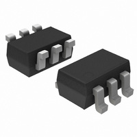
NCS2561SQT1G ON Semiconductor, NCS2561SQT1G Datasheet - Page 7

NCS2561SQT1G
Manufacturer Part Number
NCS2561SQT1G
Description
IC OP AMP HS W/FILTER SC-88
Manufacturer
ON Semiconductor
Datasheet
1.NCS2561SQT1G.pdf
(11 pages)
Specifications of NCS2561SQT1G
Applications
Filter
Number Of Circuits
1
Current - Supply
6mA
Current - Output / Channel
50mA
Voltage - Supply, Single/dual (±)
2.7 V ~ 3.3 V
Mounting Type
Surface Mount
Package / Case
6-TSSOP, SC-88, SOT-363
Lead Free Status / RoHS Status
Lead free / RoHS Compliant
Available stocks
Company
Part Number
Manufacturer
Quantity
Price
Part Number:
NCS2561SQT1G
Manufacturer:
ON/安森美
Quantity:
20 000
Sag Correction
traditionally recommend a large coupling capacitor (220 mF)
on the output of the video driver. Larger output coupling
capacitors (≥ 470 mF) are often chosen by design engineers
when the application allows this (Set−Top Box). A larger
output coupling capacitor allows a lower cut−off frequency
to avoid field tilt effects; however in portable applications
there is a trade−off between large and expensive coupling
produces a low cutoff frequency of 5 Hz, and a 470 mF
capacitor will give a low cutoff frequency at 2.6 Hz. The
cutoff frequency (−3 dB) is defined by the equation:
1/(2pR
a low Cout value can adversely affect the low cutoff
Video
DAC
Video drivers that do not incorporate sag compensation
Calculations show that a 220 mF output capacitor
L
Cout). In the case where no sag is used (Figure 14),
1 V
0 V
Rs
−10
−15
−20
−25
−30
20
15
10
−5
5
0
Figure 11. Simulation Results with Csag = 22 mF and Variable Cout
Cout = 22uF
NCS2561
IN
1
Shifter
Level
10
Figure 12. Sag Correction Configuration
2−pole
Cout = 47uF
filter
100
GND
2.7V to 3.3V
Vcc
Vcc
Gain VS Frequency
http://onsemi.com
1000
Frequency (Hz)
Cout = 67uF
+
−
Enable
10000
7
capacitors, and a coupling configuration to saving space.
The sag compensation circuitry allows the reduction of this
output coupling capacitor value by inducing peaking at the
lower cutoff frequency of the high pass filter. The high−pass
filter is created by the coupling capacitor and the load
resistor (1/(2pR
frequency. Simulation results provided in Figure 11 show
the effect of the sag compensation at the low cut−off
frequency.
frequency; the cut−off frequency will be in the critical 50 Hz
or 60 Hz frequencies. This undesirable affect will manifest
itself as field tilt. Due to the SAG correction the large output
capacitor is reduced without degrading the video
performances by the use of two smaller and cheaper output
capacitors.
Enable
100000
Cout = 100uF
1000000 10000000 1E+08
SAG
OUT
L
Cout), and this peaking lowers the cutoff
47 mF / 67 mF
22 mF
Cout = 220uF
75 W
TV
75 W


