ISL55033IRTZ Intersil, ISL55033IRTZ Datasheet - Page 11
ISL55033IRTZ
Manufacturer Part Number
ISL55033IRTZ
Description
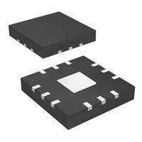
IC GAIN BLOCK R-R 400MHZ 12TQFN
Manufacturer
Intersil
Datasheet
1.ISL55033IRTZ-T13.pdf
(12 pages)
Specifications of ISL55033IRTZ
Applications
General Purpose
Output Type
Rail-to-Rail
Number Of Circuits
3
-3db Bandwidth
400MHz
Slew Rate
2350 V/µs
Current - Supply
21.3mA
Current - Output / Channel
50mA
Voltage - Supply, Single/dual (±)
3 V ~ 5.5 V
Mounting Type
Surface Mount
Package / Case
12-TQFN
Lead Free Status / RoHS Status
Lead free / RoHS Compliant


Limiting the Output Current
No output short circuit current limit exists on these parts. All
applications need to limit the output current to less than 40mA.
Adequate thermal heat sinking of the parts is also required.
PC Board Layout
The AC performance of this circuit depends greatly on the
care taken in designing the PC board. The following are
recommendations to achieve optimum high frequency
performance from your PC board.
• The use of low inductance components, such as chip
• Minimize signal trace lengths. Trace inductance and
• Match channel-to-channel analog I/O trace lengths and
• Maximize use of AC decoupled PCB layers. All signal I/O
• Use proper value and location of termination resistors. Input
Intersil products are sold by description only. Intersil Corporation reserves the right to make changes in circuit design, software and/or specifications at any time without
notice. Accordingly, the reader is cautioned to verify that data sheets are current before placing orders. Information furnished by Intersil is believed to be accurate and
reliable. However, no responsibility is assumed by Intersil or its subsidiaries for its use; nor for any infringements of patents or other rights of third parties which may result
from its use. No license is granted by implication or otherwise under any patent or patent rights of Intersil or its subsidiaries.
resistors and chip capacitors, is strongly recommended.
capacitance can easily limit circuit performance. Avoid
sharp corners. Use rounded corners when possible. Vias
in the signal lines add inductance at high frequency and
should be avoided. PCB traces greater than 1" begin to
exhibit transmission line characteristics with signal rise/fall
times of 1ns or less. High frequency performance may be
degraded for traces greater than one inch, unless
controlled impedance (50Ω or 75Ω) strip lines or
microstrips are used.
layout symmetry. This will minimize propagation delay
mismatches.
lines should be routed over continuous ground planes (i.e. no
split planes or PCB gaps under these lines). Avoid vias in the
signal I/O lines.
termination resistors should be as close to the input terminal
All Intersil U.S. products are manufactured, assembled and tested utilizing ISO9000 quality systems.
Intersil Corporation’s quality certifications can be viewed at www.intersil.com/design/quality
For information regarding Intersil Corporation and its products, see www.intersil.com
11
ISL55033
• When testing, use good quality connectors and cables,
• A minimum of 2 power supply decoupling capacitors are
• The NIC pins are placed on both sides of the input pins.
The QFN Package Requires Additional PCB Layout
Rules for the Thermal Pad
The thermal pad is electrically connected to power supply
ground through the high resistance IC substrate. Its primary
function is to provide heat sinking for the IC. However,
because of the connection to the power ground pins through
the substrate, the thermal pad must be tied to the power
supply ground to prevent unwanted current flow through the
thermal pad. Maximum AC performance is achieved if the
thermal pad has good contact to the IC ground pins. Heat
sinking requirements can be satisfied using thermal vias
directly beneath the thermal pad to a heat dissipating layer
of a square at least 1” on a side.
as possible and output termination resistors as close to the
receiving device as possible.
matching cable types and keeping cable lengths to a
minimum.
recommended (1000pF, 0.01µF) as close to the devices as
possible. Avoid vias between the capacitor and the device
because vias add unwanted inductance. Larger capacitors
can be farther away. When vias are required in a layout, they
should be routed as far away from the device as possible.
These pins are not internally connected to the die. It is
recommended these pins be tied to ground to minimize
crosstalk.
September 11, 2008
FN6346.0
Related parts for ISL55033IRTZ
Image
Part Number
Description
Manufacturer
Datasheet
Request
R

Part Number:
Description:
400mhz Slew Rate Enhanced Rail-to-rail Output Gain Block
Manufacturer:
Intersil Corporation
Datasheet:
Part Number:
Description:
Intersil Corporation [CMOS Serial Controller Interface]
Manufacturer:
Intersil Corporation
Datasheet:
Part Number:
Description:
Manufacturer:
Intersil Corporation
Datasheet:
Part Number:
Description:
357-036-542-201 CARDEDGE 36POS DL .156 BLK LOPRO
Manufacturer:
Intersil Corporation
Datasheet:
Part Number:
Description:
1024-Word x 4-Bit LSI Static RAM
Manufacturer:
Intersil Corporation
Datasheet:
Part Number:
Description:
General Purpose NPN Transistor Arrays FN341.4
Manufacturer:
Intersil Corporation
Datasheet:
Part Number:
Description:
CMOS 16-Bit Microprocessor
Manufacturer:
Intersil Corporation
Datasheet:
Part Number:
Description:
Manufacturer:
Intersil Corporation
Datasheet:
Part Number:
Description:
Manufacturer:
Intersil Corporation
Datasheet:
Part Number:
Description:
Manufacturer:
Intersil Corporation
Datasheet:
Part Number:
Description:
Manufacturer:
Intersil Corporation
Datasheet:
Part Number:
Description:
CMOS 6-Bit Latch and Decoder Memory Interfaces
Manufacturer:
Intersil Corporation
Datasheet:
Part Number:
Description:
CA3046General Purpose NPN Transistor Arrays
Manufacturer:
Intersil Corporation
Datasheet:
Part Number:
Description:
Manufacturer:
Intersil Corporation
Datasheet:
Part Number:
Description:
TR909 DLC/FLC SLIC with Low Power Standby
Manufacturer:
Intersil Corporation
Datasheet: