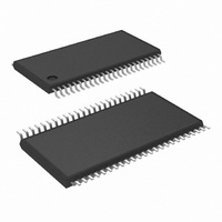
LM8207MTX/NOPB National Semiconductor, LM8207MTX/NOPB Datasheet - Page 13

LM8207MTX/NOPB
Manufacturer Part Number
LM8207MTX/NOPB
Description
IC BUFFER/DVR/VREF 48-TSSOP
Manufacturer
National Semiconductor
Datasheet
1.LM8207MTNOPB.pdf
(22 pages)
Specifications of LM8207MTX/NOPB
Applications
TFT-LCD Panels: Gamma Buffer, VCOM Driver
Output Type
Rail-to-Rail
Number Of Circuits
18
-3db Bandwidth
2MHz
Slew Rate
1 V/µs
Current - Supply
6.5mA
Current - Output / Channel
50mA
Voltage - Supply, Single/dual (±)
6 V ~ 16 V
Mounting Type
Surface Mount
Package / Case
48-TFSOP (0.240", 6.10mm Width)
Lead Free Status / RoHS Status
Lead free / RoHS Compliant
Other names
LM8207MTX
Application Section
To calculate the output voltage of the Voltage Reference
Amplifier (OUT_V
As can be seen in the Electrical Characteristics Table on
page 3, I
values for R
10 and OUT_V
−10 nA*9 kΩ = −90 µV. This error can be neglected. The
simplified formula for calculating the OUT_V
Example:
V
OUT_V
Choose R
R
THE OPERATING RANGE OF THE VOLTAGE
REFERENCE
The output of the Voltage Reference Amplifier has a mini-
mum of 1.295V (R
the internal reference. The maximum output voltage
(OUT_V
The voltage is limited by the output resistance (R
output stage of the internal amplifier and depends on the
load current. Figure 5 shows the operating output voltage
range.
DD
1
= 50.6 kΩ
= 16V
FIGURE 4. Typical Application Circuit for V
REF
REFMAX
IN_V REF
2
= 14.4V
1
= 5 kΩ. Using Equation (2), this will result in
= 9 kΩ and R
REF
) can approach the positive supply rail V
has a typical value of −10 nA. Using resistor
REF
1
= 12.95 V an error will be introduced of
= 0). This is determined by the value of
) use the following equation:
2
= 1 kΩ this results in a gain of
(Continued)
REF
is:
OUT
REF
) of the
20137925
DD
(1)
(2)
.
13
The minimum headroom (OUT_V
positive supply rail V
circuit shown in Figure 6.
The headroom is measured by varying both the supply volt-
age and the output current (I
value of OUT_V
headroom slightly increases for a constant V
load current increases.
FIGURE 6. Headroom Test Circuit with Variable Output
FIGURE 5. Operating Output Voltage Range
REF
. As shown in Figure 7, the minimum
DD
Current Load
) can be measured using the test
LOAD
) for a fixed programmed
REF
with respect to the
DD
20137921
www.national.com
when the
20137924


