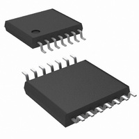
LM6588MTX/NOPB National Semiconductor, LM6588MTX/NOPB Datasheet - Page 11

LM6588MTX/NOPB
Manufacturer Part Number
LM6588MTX/NOPB
Description
IC OPAMP TFT-LCD QD 16V 14-TSSOP
Manufacturer
National Semiconductor
Series
VIP10™r
Datasheet
1.LM6588MANOPB.pdf
(16 pages)
Specifications of LM6588MTX/NOPB
Applications
TFT-LCD Panels: Gamma Buffer, VCOM Driver
Output Type
Rail-to-Rail
Number Of Circuits
4
-3db Bandwidth
24MHz
Slew Rate
15 V/µs
Current - Supply
800µA
Current - Output / Channel
230mA
Voltage - Supply, Single/dual (±)
5 V ~ 16 V, ±2.5 V ~ 8 V
Mounting Type
Surface Mount
Package / Case
14-TSSOP (0.173", 4.40mm Width)
Number Of Channels
4
Voltage Gain Db
106 dB
Common Mode Rejection Ratio (min)
70 dB
Input Offset Voltage
4 mV at 5 V
Operating Supply Voltage
9 V, 12 V, 15 V
Supply Current
4 mA at 5 V
Maximum Operating Temperature
+ 85 C
Maximum Dual Supply Voltage
+/- 8 V
Minimum Operating Temperature
- 40 C
Lead Free Status / RoHS Status
Lead free / RoHS Compliant
Other names
LM6588MTX
Available stocks
Company
Part Number
Manufacturer
Quantity
Price
Company:
Part Number:
LM6588MTX/NOPB
Manufacturer:
NS/TI
Quantity:
6
TFT Display Application
light filter that modulates light transmitted from the back to
the front of a display. A pixel’s bottom plate lies on the
backside of a display where a light source is applied, and the
top plate lies on the front, facing the viewer. On a Twisted
Neumatic (TN) display, which is typical of most TFT displays,
a pixel transmits the greatest amount of light when V
less
increases with either a positive or negative polarity. In short,
an LCD pixel can be thought of as a capacitor, through
which, a controlled amount of light is transmitted by varying
V
Figure 2 is a simplified block diagram of a TFT display,
showing how individual pixels are connected to the row,
column, and V
pacitor with an NMOS transistor connected to its top plate.
Pixels in a TFT panel are arranged in rows and columns.
Row lines are connected to the NMOS gates, and column
lines to the NMOS sources. The back plate of every pixel is
connected to a common voltage called V
ness is controlled by voltage applied to the top plates, and
PIXEL
±
0.5V, and it becomes less transparent as this voltage
.
FIGURE 1. Individual LCD Pixel
COM
FIGURE 2. TFT Display
lines. Each pixel is represented by ca-
COM
(Continued)
. Pixel bright-
20073426
20073427
PIXEL
is
11
the Column Drivers supply this voltage via the column lines.
Column Drivers ‘write’ this voltage to the pixels one row at a
time, and this is accomplished by having the Row Drivers
select an individual row of pixels when their voltage levels
are transmitted by the Column Drivers. The Row Drivers
sequentially apply a large positive pulse (typically 25V to
35V) to each row line. This turns-on NMOS transistors con-
nected to an individual row, allowing voltages from the col-
umn lines to be transmitted to the pixels.
V
The V
the pixels in a TFT panel. V
lies in the middle of the column drivers’ output voltage range.
As a result, when the column drivers write to a row of pixels,
they apply voltages that are either positive or negative with
respect to V
each time its row is selected. This allows the column drivers
to apply an alternating voltage to the pixels rather than a DC
signal, which can ‘burn’ a pattern into an LCD display.
When column drivers write to the pixels, current pulses are
injected onto the V
ing stray capacitance between V
(see Figure 2), which ranges typically from 16pF to 33pF per
column. Pixel capacitance contributes very little to these
pulses because only one pixel at a time is connected to a
column, and the capacitance of a single pixel is on the order
of only 0.5pF. Each column line has a significant amount of
series resistance (typically 2kΩ to 40kΩ), so the stray ca-
pacitance is distributed along the entire length of a column.
This can be modeled by the multi-segment RC network
shown in Figure 3. The total capacitance between V
the column lines can range from 25nF to 100nF, and charg-
ing this capacitance can result in positive or negative current
pulses of 100mA, or more. In addition, a similar distributed
capacitance of approximately the same value exists be-
tween V
load is the sum of these distributed RC networks with a total
capacitance of 50nF to 200nF, and this load can modeled
like the circuit in Figure 3.
A V
source and sink current into a large capacitive load. To
simplify the analysis of this driver, the distributed RC network
of Figure 3 has been reduced to a single RC load in Figure
4. This load places a large capacitance on the V
output, resulting in an additional pole in the op amp’s feed-
back loop. However, the op amp remains stable because
C
pole. The range of C
to 100Ω, so this zero will have a frequency in the range of
COM
LOAD
FIGURE 3. Model of Impedance between V
COM
COM
DRIVER
and R
COM
driver is essentially a voltage regulator that can
driver supplies a common voltage (V
COM
and the row lines. Therefore, the V
ESR
. In fact, the polarity of a pixel is reversed
create a zero that cancels the effect of this
COM
LOAD
Column Lines
line. These pulses result from charg-
is 50nF to 200nF and R
COM
is a constant DC voltage that
COM
and the column lines
COM
COM
www.national.com
COM
ESR
COM
20073428
COM
driver’s
) to all
and
is 20Ω
driver
and


