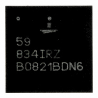
ISL59834IRZ Intersil, ISL59834IRZ Datasheet

ISL59834IRZ
Specifications of ISL59834IRZ
Related parts for ISL59834IRZ
ISL59834IRZ Summary of contents
Page 1
... RANGE PACKAGE (NOTE) MARKING (°C) ISL59834IRZ 59 834IRZ - QFN NOTE: These Intersil Pb-free plastic packaged products employ special Pb-free material sets, molding compounds/die attach materials, and 100% matte tin plate plus anneal (e3 termination finish, which is RoHS compliant and compatible with both SnPb and Pb-free soldering operations) ...
Page 2
Pinout GND 1 IN2 2 GND 3 GND 4 CPA V 5 CPA ENABLE 7 B IN3 8 GND 9 IN4 10 GND 11 2 ISL59834 ISL59834 (44 LD QFN) TOP VIEW ...
Page 3
... Power Supply Rejection DC 3 ISL59834 Thermal Information Thermal Resistance (Typical, Note 1) + 0.3V 44 Lead QFN . . . . . . . . . . . . . . . . . . . . . . . . . . . . . . S Maximum Junction Temperature (Plastic Package +150°C Maximum Storage Temperature Range . . . . . . . . . .-65°C to +150°C Pb-free reflow profile . . . . . . . . . . . . . . . . . . . . . . . . . .see link below http://www.intersil.com/pbfree/Pb-FreeReflow.asp = 3.3V 0.1µ 0.22µ ...
Page 4
Electrical Specifications 0.1µF, R SYMBOL PARAMETER AC CHARACTERISTICS A Passband Flatness PB A Stopband Attenuation SB dG Differential Gain dP Differential Phase SNR Signal-to-Noise Ratio GD DC Group Delay Match MATCH ΔGD Group Delay Deviation PSRR ...
Page 5
Pin Descriptions NUMBER NAME GND 2 IN2 4 GND CPA 5 V CPA ENABLE B 8 IN3 10 IN4 12, 13, 16, 17, 18, NC 21, 35, 38, 40 ...
Page 6
Functional Diagram SYNC_OUTA SYNC DETECTOR IN1 IN2 SYNC_OUTB SYNC DETECTOR IN3 IN4 VEEA IN VEEB IN ISL59834 VEEA GND OUT 6 ISL59834 V S LPF LEVEL SHIFT (-310mV) 9MHz - + -593mV LPF LEVEL SHIFT (-165mV) 9MHz - KEYED + ...
Page 7
Component (YPbPr) Application Diagram ENABLE 0.1µF Y CURRENT IN1 DAC 150Ω 0.1µF PB CURRENT IN2 DAC 150Ω 0.1µF PR CURRENT IN4 DAC 150Ω MPEG DECODER 0.1µF COMPOSITE IN3 SOURCE 75Ω VEEA R 10Ω FIL1 VEEA 0.22µF 0.47µ ...
Page 8
S-Video Application Diagram ENABLE 0.1μF IN1 Y1 75Ω 0.1μF C1 IN2 75Ω 0.1μF Y2 IN3 75Ω 0.1μF IN4 C2 75Ω VEEA 10Ω R FIL1 VEEA 0.47μF 0.22μ FIL1 +3.3V V CPA 1.0μF 0.1μF C GND C CP1B ...
Page 9
Typical Performance Curves 10 0 -10 CHANNEL 2, 4 -20 = 150 Ω -30 -40 CHANNEL 150 Ω R -50 L -60 CHANNEL -70 0.1 1M FREQUENCY (Hz) FIGURE 1. BANDWIDTH ...
Page 10
Typical Performance Curves 0 INPUT OF CHANNEL OUTPUT OF -10 CHANNEL 2, 4 AND VICE-VERSA -20 -30 -40 -50 -60 -70 0.1 1M FREQUENCY (Hz) FIGURE 7. LUMA-TO-CHROMA CROSSTALK 1500 NO LOAD 1400 INPUT FLOATING 1300 1200 ...
Page 11
Typical Performance Curves 0.6 WAVEFORM = MODULATED RAMP 0.5 0 IRE to 100 IRE 0.4 0.3 0.2 0.1 0 -0.1 -0 STEP FIGURE 13. DIFFERENTIAL PHASE TIME SCALE = 5µs/DIV ENABLE = 1V/DIV ...
Page 12
Typical Performance Curves TIME SCALE = 10µs/DIV LUMA OUT = 500mV/DIV LUMA OUTPUT CHROMA OUT = 500mV/DIV CHANNELS 1, 3 CHROMA OUTPUT CHANNELS 2, 4 FIGURE 19. S-VIDEO SCOPE SHOT INPUT = NTSC VIDEO + 2Hz SQUARE WAVE (BEFORE COUPLING ...
Page 13
Typical Performance Curves 100 RMS NOISE = 2.87mV OUTPUT REFERRED 10 CHARGE PUMP NOISE, CONTRIBUTES ONLY A SMALL PERCENTAGE OF THE OVERALL NOISE 1 0 FREQUENCY (Hz) FIGURE 25. NOISE SPECTRUM 0 V ...
Page 14
To reduce the noise on the power supply generated by the charge pump, connect a lowpass RC-network between VEE and VEE . See the “Typical Application Circuits” OUT IN for further ...
Page 15
When disabled, the device supply current is reduced to 5µA. Power-down is controlled by standard TTL or CMOS signal levels at the ...
Page 16
Use good quality connectors and cables, matching cable types and keeping cable lengths to a minimum when testing. • Place flying and output capacitors as close to the device as possible for the charge pump. Decouple well, using a ...
Page 17
... Accordingly, the reader is cautioned to verify that data sheets are current before placing orders. Information furnished by Intersil is believed to be accurate and reliable. However, no responsibility is assumed by Intersil or its subsidiaries for its use; nor for any infringements of patents or other rights of third parties which may result from its use ...


