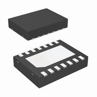
LMH6722QSD/NOPB National Semiconductor, LMH6722QSD/NOPB Datasheet - Page 12

LMH6722QSD/NOPB
Manufacturer Part Number
LMH6722QSD/NOPB
Description
IC OP AMP QUAD VIDEO 14-LLP
Manufacturer
National Semiconductor
Series
PowerWise®, VIP10™r
Datasheet
1.LMH6714MFNOPB.pdf
(16 pages)
Specifications of LMH6722QSD/NOPB
Applications
Current Feedback
Number Of Circuits
4
-3db Bandwidth
400MHz
Slew Rate
1800 V/µs
Current - Supply
5.6mA
Current - Output / Channel
70mA
Voltage - Supply, Single/dual (±)
8 V ~ 12.5 V, ±4 V ~ 6.25 V
Mounting Type
Surface Mount
Package / Case
14-LLP
Lead Free Status / RoHS Status
Lead free / RoHS Compliant
Other names
LMH6722QSDTR
www.national.com
FIGURE 9. Digital Signal without and with Equalization
FIGURE 8. Equalizer Circuit Schematic
FIGURE 10. Design Equations
20056530
20056529
20056522
12
POWER DISSIPATION
Follow these steps to determine the Maximum power dissi-
pation for the LMH6714/LMH6720/LMH6722:
1. Calculate the quiescent (no load) power: P
2. Calculate the RMS power at the output stage:
3. Calculate the total RMS power: P
The maximum power that the LMH6714/LMH6720/LMH6722,
package can dissipate at a given temperature can be derived
with the following equation:
P
C) and θ
a given package (°C/W). For the SOIC package θ
W, for the SOT it is 250°C/W.
MAX
(V
P
V
ternal load.
OUT
OUT
CC
= (150° - T
FIGURE 11. Equalizer Frequency Response
JA
-V
(RMS) = ((V
and I
= Thermal resistance, from junction to ambient, for
EE
)
OUT
A
)/ θ
are the voltage and current across the ex-
CC
JA
, where T
- V
OUT
(RMS)) * I
A
= Ambient temperature (°
T
= P
OUT
AMP
(RMS)), where
+ P
20056517
JA
OUT
AMP
is 148°C/
= I
CC


