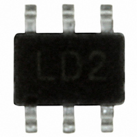
ISL59112IEZ-T7 Intersil, ISL59112IEZ-T7 Datasheet - Page 6

ISL59112IEZ-T7
Manufacturer Part Number
ISL59112IEZ-T7
Description
IC VIDEO BUFFER 40MHZ R-R SC70-6
Manufacturer
Intersil
Datasheet
1.ISL59112IEZ-T7.pdf
(8 pages)
Specifications of ISL59112IEZ-T7
Applications
Buffer
Output Type
Rail-to-Rail
Number Of Circuits
1
-3db Bandwidth
40MHz
Slew Rate
85 V/µs
Current - Supply
2mA
Current - Output / Channel
115mA
Voltage - Supply, Single/dual (±)
2.5 V ~ 3.6 V
Mounting Type
Surface Mount
Package / Case
6-TSSOP, SC-88, SOT-363
Lead Free Status / RoHS Status
Lead free / RoHS Compliant
Other names
ISL59112IEZ-T7TR
Available stocks
Company
Part Number
Manufacturer
Quantity
Price
Company:
Part Number:
ISL59112IEZ-T7
Manufacturer:
INTERSIL
Quantity:
52 000
Part Number:
ISL59112IEZ-T7
Manufacturer:
INTERSIL
Quantity:
20 000
FIGURE 12. SAG NETWORK AND AC COUPLING CAPACITORS
Typically, this is accomplished with 220µF coupling
capacitor, a large and somewhat costly solution providing a
low frequency pole around 5Hz. If the size of this capacitor is
even slightly reduced we have found that the accompanying
phase shift in the 50Hz to 100Hz frequency range results in
field tilt, which results in a degraded video image.
The internal SAG network of the ISL59112 replaces the
220µF AC coupling capacitor with a network of two smaller
capacitors as shown, in Figure 12. Additionally, the network
is designed to place a zero in the ~30Hz range, providing a
small amount of peaking to compensate the phase response
associated with field tilt.
DC Output Coupling
The ISL59112 internal sync clamp makes it possible to DC
couple the output to a video load, eliminating the need for
any AC coupling capacitor, thereby saving board space and
additional expense for capacitors. Additionally, this solution
completely eliminates the issue of field tilt in the lower
frequency. The trade off is greater demand of supply current.
Typical load current for AC coupled is around 3mA
compared to typical 6mA used when DC coupling.
Output Drive Capability
The ISL59112 does not have internal short-circuit protection
circuitry. If the output is shorted indefinitely, the power
dissipation could easily overheat the die or the current could
eventually compromise metal integrity. Maximum reliability is
maintained if the output current never exceeds ±40mA. This
limit is set by the design of the internal metal interconnect.
Note that in transient applications, the part is robust.
+
-
ENABLE
NETWORK
SAG
R
R
R
FIGURE 13. DC COUPLE
6
5
4
R
7
AC COUPLING
CAPACITOR
R
OUT
6
C
C
5
4
R
OUT
TELEVISION
OR VCR
R
L
ISL59112
Short-circuit protection can be provided externally with a
back match resistor in series with the output placed close as
possible to the output pin. In video applications this would be
a 75Ω resistor and will provide adequate short-circuit
protection to the device. Care should still be taken not to
stress the device with a short at the output.
Power Dissipation
With the high output drive capability of the ISL59112, it is
possible to exceed the +125°C absolute maximum junction
temperature under certain load current conditions.
Therefore, it is important to calculate the maximum junction
temperature for an application to determine if load conditions
or package types need to be modified to assure operation of
the amplifier in a safe operating area.
The maximum power dissipation allowed in a package is
determined according to Equation 1:
PD
Where:
The maximum power dissipation actually produced by an IC
is the total quiescent supply current times the total power
supply voltage, plus the power in the IC due to the load, or
for sourcing:
PD
for sinking:
PD
Where:
By setting the two P
can solve the output current and R
overheat.
T
T
Θ
V
I
V
R
I
MAX
MAX
MAX
SMAX
LOAD
AMAX
JMAX
S
OUT
LOAD
JA
= Supply voltage
= Thermal resistance of the package
=
=
=
= Maximum output voltage of the application
= Load current
= Maximum quiescent supply current
= Maximum junction temperature
= Maximum ambient temperature
= Load resistance tied to ground
T
-------------------------------------------- -
V
V
JMAX
S
S
×
×
I
I
SMAX
SMAX
Θ
–
JA
T
DMAX
AMAX
+
+
(
(
V
V
S
OUT
equations equal to each other, we
–
V
i V
OUT
–
S
i
LOAD
)
)
×
×
I
V
-----------------
LOAD
OUT
R
L
to avoid the device
i
i
i
March 15, 2007
FN6142.4
(EQ. 1)
(EQ. 2)
(EQ. 3)


