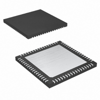
MAX2078CTK+ Maxim Integrated Products, MAX2078CTK+ Datasheet - Page 19

MAX2078CTK+
Manufacturer Part Number
MAX2078CTK+
Description
IC FRNT-END ULTRASOUND 8CH 68QFN
Manufacturer
Maxim Integrated Products
Type
Ultrasound Receiversr
Datasheet
1.MAX2078CTK.pdf
(26 pages)
Specifications of MAX2078CTK+
Applications
Medical Ultrasound Imaging, Sonar
Mounting Type
Surface Mount
Package / Case
68-TQFN Exposed Pad
Operating Supply Voltage
3.13 V to 3.47 V
Maximum Operating Temperature
+ 70 C
Mounting Style
SMD/SMT
Minimum Operating Temperature
0 C
Lead Free Status / RoHS Status
Lead free / RoHS Compliant
During normal operation, the MAX2078 is configured so
that either the VGA path is enabled while the mixer
array is powered down (VGA mode), or the quadrature
mixer array is enabled while the VGA path is powered
down (CW mode). For VGA mode, set V/C to a logic-
high and for CW mode, set V/C to a logic-low.
The MAX2078 can also be powered down with PD. Set
PD to V
mode, the device draws a total supply current less than
1µA. Set PD to logic-low for normal operation.
A low-power mode is available to lower the required
power for CWD operation. When selected, the complex
mixers operate at lower quiescent currents and the total
per-channel current is lowered to 34.2mA. Note that
operation in this mode slightly reduces the dynamic
performance of the device. Table 4 shows the logic
function of the standard operating modes.
The mode select response time is the time that the
device takes to switch between CW and VGA modes.
Figure 2 depicts one possible approach to interfacing
the CW outputs to an instrumentation amplifier, which is
used to drive an ADC. In this implementation, there are
four large-value (in the range of 470nF to 1µF) capaci-
tors between each of the CQ+, CQ-, CI+, CI- outputs
and the circuitry they are driving. The output of the CW
Table 4. Logic Function of Standard Operating Modes
N/A = Not applicable.
INPUT
PD
1
1
0
0
0
CC1
V/C
Power-Down and Low-Power Mode
1
0
0
0
1
for power-down mode. In power-down
Applications Information
VGA and CW Mixer Operation
______________________________________________________________________________________
CLP
Mode Select Response Time
N/A
N/A
N/A
0
1
VGA
Off
Off
Off
Off
On
Octal-Channel Ultrasound Front-End
MIXER
CW
Off
Off
On
On
Off
INTERNAL
SWITCH
TO VGA
Off
Off
Off
Off
On
INTERNAL
SWITCH
TO CW
MIXER
with CW Doppler Mixers
Off
Off
On
On
Off
mixer usually drives the input of an instrumentation
amplifier made up of op amps whose input impedance
is set by common-mode setting resistors.
There are clearly both a highpass corner and a lowpass
corner present in this output network. The lowpass cor-
ner is set primarily by the 162Ω mixer pullup resistors,
the series 50Ω resistors, and the shunt 0.022µF capaci-
tor. This lowpass corner is used to filter a combination
of LO leakage and upper sideband. The highpass cor-
ner, however, is of a larger concern since it is dominat-
ed by the combination of a 1µF DC-blocking capacitor
and the pair of shunt 31.6kΩ resistors.
Figure 2. Typical Example of a CW Mixer’s Output Circuit
162Ω
CONSUMPTION
CURRENT
CI+
CI-
3.3V V
3.2mA
3.2mA
0.3µA
0.1µA
88mA
162Ω
CC
50Ω
CONSUMPTION
0.022µF
CURRENT
31.6kΩ
31.6kΩ
1µF
1µF
5V V
248mA
216mA
0.4µA
0.6µA
48mA
CC
CONSUMPTION
CURRENT
11V V
90.4mA
54.4mA
0
0
0
MIX
19


