TL082SG-13 Diodes Inc, TL082SG-13 Datasheet - Page 4
TL082SG-13
Manufacturer Part Number
TL082SG-13
Description
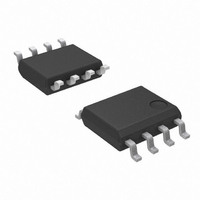
IC OPAMP JFET DUAL 8-SOIC
Manufacturer
Diodes Inc
Datasheet
1.TL082SG-13.pdf
(11 pages)
Specifications of TL082SG-13
Amplifier Type
J-FET
Number Of Circuits
2
Slew Rate
13 V/µs
Gain Bandwidth Product
3MHz
Current - Input Bias
30pA
Voltage - Input Offset
3000µV
Current - Supply
1.4mA
Voltage - Supply, Single/dual (±)
10 V ~ 30 V, ±5 V ~ 15 V
Operating Temperature
-40°C ~ 85°C
Mounting Type
Surface Mount
Package / Case
8-SOIC (3.9mm Width)
Lead Free Status / RoHS Status
Lead free / RoHS Compliant
Output Type
-
Current - Output / Channel
-
-3db Bandwidth
-
Lead Free Status / Rohs Status
Details
Other names
TL082SG-13DITR
Available stocks
Company
Part Number
Manufacturer
Quantity
Price
Company:

Part Number:
TL082SG-13
Manufacturer:
ADI
Quantity:
750
Part Number:
TL082SG-13
Manufacturer:
DIODES/美台
Quantity:
20 000


Electrical Characteristics
Notes:
TL082 Rev. 1
Symbol
V
CMRR
O1
THD
V
k
V
α
A
SR
V
θ
θ
I
Vn
B
I
v
I
SVR
In
CC
tr
ICR
r
IO
IB
OM
VD
/V
JA
JC
IO
i
IO
1
O2
9. Test condition for SOP-8L: Devices mounted on FR-4 substrate PC board, with minimum recommended pad layout.
Input Offset Voltage
Temperature Coefficient
of Input Offset Voltage
Input Offset Current
Input Bias Current
Common Mode
Input Voltage Range
Maximum Peak
Output Voltage Swing
Large Signal Differential
Voltage Amplification
Unity Gain Bandwidth
Input Resistance
Common Mode
Rejection Ratio
Supply Voltage
Rejection Ratio
(ΔV
Supply Current
(each amplifier)
Crosstalk Attenuation
Slew Rate at Unity Gain
Rise Time
Overshoot Factor
Equivalent Input Noise
Voltage
Equivalent Input Noise
Current
Total Harmonic
Distortion
Thermal Resistance
Junction-to-Ambient
Thermal Resistance
Junction-to-Case
CC
±/ΔV
Parameter
IO
)
V
R
V
V
V
R
R
R
V
R
T
V
R
V
V
R
V
No load
A
V
R
(See Figure 1)
V
(See Figure 1)
R
R
V
R
f=1kHz
SOP-8L (Note 9)
SOP-8L (Note 9)
A
O
O
O
O
O
IC
CC
O
O
VD
I
I
Irms
S
L
L
L
L
S
S
L
S
S
L
=10V, C
=20mV, R
=25
=10kΩ, T
≧10kΩ,
≧2kΩ
≧2kΩ
=2kΩ
≧2kΩ, R
=0,
=50Ω
=0, R
=0
=0
=±10V,
=50Ω, T
=0
=50Ω, T
=0, T
=20Ω
=20Ω, f=1kHz
=V
=±9 to ±15V
=100, T
=6V, A
(V
ICRmin
o
CC±
C
A
S
GENERAL PURPOSE JFET INPUT OPERATIONAL
=25
Test Conditions
=50Ω, T
www.diodes.com
L
, V
A
A
=100pF,
VD
A
= ±15V, T
A
=25
=25
S
L
=25
=25
≦1kΩ,
=2kΩ, C
o
=1,
O
f=1kHz
f=10 Hz to 10kHz
C
=0
4 of 11
o
o
o
C
C
o
A
C
C
= full range
T
T
T
T
T
T
T
T
T
T
T
L
A
=100pF
A
A
A
A
A
A
A
A
A
A
A
= 25
=25
= full range
=25
= full range
=25
= full range
= full range
=25
= full range
=25
= full range
o
o
o
o
o
o
C
C
C
C
C
C; unless otherwise noted)
Min
±11
±12
±12
±10
50
25
75
80
8
5
-12~+15
±13.5
0.003
Typ.
0.05
0.01
10
±12
200
120
145
1.4
18
30
86
86
13
20
18
35
3
5
3
4
12
AMPLIFIERS
©
Max
100
200
2.8
10
20
Diodes Incorporated
6
9
TL082
JULY 2009
pA
nV
μV/
V/mV
o
o
MHz
V/μs
Unit
mV
mA
C/W
C/W
pA
nA
pA
nA
dB
dB
dB
μV
μs
%
%
Ω
V
V
o
ΗΖ
HZ
C
Related parts for TL082SG-13
Image
Part Number
Description
Manufacturer
Datasheet
Request
R

Part Number:
Description:
Diodes (General Purpose, Power, Switching) 240V 350mW
Manufacturer:
Diodes Inc
Datasheet:

Part Number:
Description:
Diodes (General Purpose, Power, Switching) -
Manufacturer:
Diodes Inc
Part Number:
Description:
Diodes (General Purpose, Power, Switching) -
Manufacturer:
Diodes Inc

Part Number:
Description:
Diodes (General Purpose, Power, Switching) NPN Small SIG 50V 45V VCEO 6.0V VEBO
Manufacturer:
Diodes Inc
Datasheet:
Part Number:
Description:
Diodes (General Purpose, Power, Switching) NPN Small SIG 30V 30V VCEO 5.0V VEBO
Manufacturer:
Diodes Inc
Datasheet:
Part Number:
Description:
Diodes (General Purpose, Power, Switching) NPN Small SIG -80V -65V VCEO -5.0 VEBO
Manufacturer:
Diodes Inc
Datasheet:
Part Number:
Description:
Diodes (General Purpose, Power, Switching) NPN Small SIG -50V -45V VCEO 6.0V VEBO
Manufacturer:
Diodes Inc
Part Number:
Description:
Diodes (General Purpose, Power, Switching) Dual Switching DIODE 100V Vrm 75Vrrm 53Vr
Manufacturer:
Diodes Inc
Datasheet:

Part Number:
Description:
Diodes (General Purpose, Power, Switching) Vr/80V Io/125mA T/R
Manufacturer:
Diodes Inc
Datasheet:

Part Number:
Description:
Diodes (General Purpose, Power, Switching) HV DUAL SW DIODE 300V
Manufacturer:
Diodes Inc
Datasheet:

Part Number:
Description:
Diodes (General Purpose, Power, Switching) 80V 150mW
Manufacturer:
Diodes Inc
Datasheet:
Part Number:
Description:
Diodes (General Purpose, Power, Switching) 75V 150mW
Manufacturer:
Diodes Inc
Datasheet:

Part Number:
Description:
Diodes (General Purpose, Power, Switching) 200MW 80V
Manufacturer:
Diodes Inc
Part Number:
Description:
Diodes (General Purpose, Power, Switching) 100V Io/150mA T/R INVALID P/N
Manufacturer:
Diodes Inc

Part Number:
Description:
Diodes (General Purpose, Power, Switching) 350MW 75V
Manufacturer:
Diodes Inc