LM4809LD/NOPB National Semiconductor, LM4809LD/NOPB Datasheet - Page 13
LM4809LD/NOPB
Manufacturer Part Number
LM4809LD/NOPB
Description
IC AMP AUDIO PWR .105W STER 8LLP
Manufacturer
National Semiconductor
Series
Boomer®r
Type
Class ABr
Datasheet
1.LM4809MMNOPB.pdf
(21 pages)
Specifications of LM4809LD/NOPB
Output Type
Headphones, 2-Channel (Stereo)
Max Output Power X Channels @ Load
105mW x 2 @ 16 Ohm
Voltage - Supply
2 V ~ 5.5 V
Features
Depop, Shutdown, Thermal Protection
Mounting Type
Surface Mount
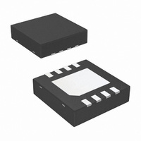
Package / Case
8-LLP
Operational Class
Class-AB
Audio Amplifier Output Configuration
2-Channel Stereo
Output Power (typ)
0.105x2@16OhmW
Audio Amplifier Function
Headphone
Total Harmonic Distortion
0.3@32Ohm@50mW%
Single Supply Voltage (typ)
3/5V
Dual Supply Voltage (typ)
Not RequiredV
Supply Current (max)
3@5VmA
Power Supply Requirement
Single
Rail/rail I/o Type
No
Power Supply Rejection Ratio
70dB
Single Supply Voltage (min)
2V
Single Supply Voltage (max)
5.5V
Dual Supply Voltage (min)
Not RequiredV
Dual Supply Voltage (max)
Not RequiredV
Operating Temp Range
-40C to 85C
Operating Temperature Classification
Industrial
Mounting
Surface Mount
Pin Count
8
Package Type
LLP
For Use With
LM4809LDBD - BOARD EVALUATION LM4809LD
Lead Free Status / RoHS Status
Lead free / RoHS Compliant
Other names
LM4809LD
LM4809LDTR
LM4809LDTR
Available stocks
Company
Part Number
Manufacturer
Quantity
Price
Company:

Part Number:
LM4809LD/NOPB
Manufacturer:
NSC
Quantity:
13 023


Application Information
find the minimum supply voltage is to use the Output Power
vs Supply Voltage curve in the Typical Performance Char-
acteristics section. Another way, using Equation (5), is to
calculate the peak output voltage necessary to achieve the
desired output power for a given load impedance. To ac-
count for the amplifier’s dropout voltage, two additional volt-
ages, based on the Dropout Voltage vs Supply Voltage in the
Typical Performance Characteristics curves, must be
added to the result obtained by Equation (5). For a single-
ended application, the result is Equation (6).
The Output Power vs Supply Voltage graph for a 32Ω load
indicates a minimum supply voltage of 4.8V. This is easily
met by the commonly used 5V supply voltage. The additional
voltage creates the benefit of headroom, allowing the
LM4809 to produce peak output power in excess of 70mW
without clipping or other audible distortion. The choice of
supply voltage must also not create a situation that violates
maximum power dissipation as explained above in the
Power Dissipation section. Remember that the maximum
power dissipation point from Equation (1) must be multiplied
by two since there are two independent amplifiers inside the
package. Once the power dissipation equations have been
addressed, the required gain can be determined from Equa-
tion (7).
Thus, a minimum gain of 1.497 allows the LM4809 to reach
full output swing and maintain low noise and THD+N perfro-
mance. For this example, let A
The amplifiers overall gain is set using the input (R
feedback (R
set at 20kΩ, the feedback resistor is found using Equation
(8).
V
DD
f
) resistors. With the desired input impedance
≥ (2V
OPEAK
+ (V
V
=1.5.
OD TOP
+ V
OD BOT
(Continued)
))
i
) and
(5)
(6)
(7)
13
The value of R
The last step in this design is setting the amplifier’s −3db
frequency bandwidth. To achieve the desired
band magnitude variation limit, the low frequency response
must extend to at lease one−fifth the lower bandwidth limit
and the high frequency response must extend to at least five
times the upper bandwidth limit. The gain variation for both
response limits is 0.17dB, well within the
limit. The results are an
and a
As stated in the External Components section, both R
conjunction with C
pass filters. Thus to obtain the desired low frequency re-
sponse of 100Hz within
into consideration. The combination of two single order filters
at the same frequency forms a second order response. This
results in a signal which is down 0.34dB at five times away
from the single order filter −3dB point. Thus, a frequency of
20Hz is used in the following equations to ensure that the
response is better than 0.5dB down at 100Hz.
The high frequency pole is determined by the product of the
desired high frequency pole, f
A
resulting GBWP = 150kHz which is much smaller than the
LM4809’s GBWP of 900kHz. This figure displays that if a
designer has a need to design an amplifier with a higher
gain, the LM4809 can still be used without running into
bandwidth limitations.
V
. With a closed-loop gain of 1.5 and f
C
C
i
≥ 1 / (2π * 20kΩ * 20Hz) = 0.397µF; use 0.39µF.(11)
o
≥ 1 / (2π * 32Ω * 20Hz) = 249µF; use 330µF. (12)
f
is 30kΩ.
f
i
H
, and C
f
L
= 20kHz
= 100Hz/5 = 20Hz
A
±
V
0.5dB, both poles must be taken
o
= R
with R
*
5 = 100kHz
H
f
, and the closed-loop gain,
/R
i
L
, create first order high-
H
±
0.25dB desired
= 100kHz, the
±
0.25dB pass
www.national.com
(10)
i
(8)
(9)
in
Related parts for LM4809LD/NOPB
Image
Part Number
Description
Manufacturer
Datasheet
Request
R

Part Number:
Description:
LM4809 Dual 105mW Headphone Amplifier with Active-Low Shutdown Mode
Manufacturer:
National Semiconductor
Datasheet:
Part Number:
Description:
National Semiconductor [8-Bit D/A Converter]
Manufacturer:
National Semiconductor
Datasheet:
Part Number:
Description:
National Semiconductor [Media Coprocessor]
Manufacturer:
National Semiconductor
Datasheet:
Part Number:
Description:
Digitally Controlled Tone and Volume Circuit with Stereo Audio Power Amplifier, Microphone Preamp Stage and National 3D Sound
Manufacturer:
National Semiconductor
Datasheet:
Part Number:
Description:
Digitally Controlled Tone and Volume Circuit with Stereo Audio Power Amplifier, Microphone Preamp Stage and National 3D Sound
Manufacturer:
National Semiconductor
Datasheet:
Part Number:
Description:
AC97 Rev 2 Codec with Sample Rate Conversion and National 3D Sound
Manufacturer:
National Semiconductor
Part Number:
Description:
Manufacturer:
National Semiconductor
Datasheet:
Part Number:
Description:
Manufacturer:
National Semiconductor
Datasheet:
Part Number:
Description:
General Purpose, Low Voltage, Low Power, Rail-to-Rail Output Operational Amplifiers
Manufacturer:
National Semiconductor
Datasheet:
Part Number:
Description:
8-bit 20 MSPS flash A/D converter.
Manufacturer:
National Semiconductor
Datasheet:
Part Number:
Description:
Low Noise Quad Operational Amplifier
Manufacturer:
National Semiconductor
Datasheet:
Part Number:
Description:
Quad Differential Line Receivers
Manufacturer:
National Semiconductor
Datasheet:
Part Number:
Description:
Quad High Speed Trapezoidal? Bus Transceiver
Manufacturer:
National Semiconductor
Datasheet:
Part Number:
Description:
Dual Line Receiver
Manufacturer:
National Semiconductor
Datasheet: