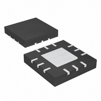
MAX9725CETC+ Maxim Integrated Products, MAX9725CETC+ Datasheet - Page 4

MAX9725CETC+
Manufacturer Part Number
MAX9725CETC+
Description
IC AMP AUDIO .025W STER 12TQFN
Manufacturer
Maxim Integrated Products
Series
DirectDrive™r
Type
Class ABr
Datasheet
1.MAX9725CETCT.pdf
(17 pages)
Specifications of MAX9725CETC+
Output Type
Headphones, 2-Channel (Stereo)
Max Output Power X Channels @ Load
25mW x 2 @ 16 Ohm
Voltage - Supply
900 mV ~ 1.8 V
Features
Depop, Short-Circuit Protection, Shutdown
Mounting Type
Surface Mount
Package / Case
12-TQFN Exposed Pad
Lead Free Status / RoHS Status
Lead free / RoHS Compliant
1V, Low-Power, DirectDrive, Stereo Headphone
Amplifier with Shutdown
ELECTRICAL CHARACTERISTICS (MAX9725E) (continued)
(V
T
Note 1: All specifications are 100% tested at T
Note 2: Input leakage current measurements limited by automated test equipment.
Note 3: f
Note 4: Testing performed with 32Ω resistive load connected to outputs. Mode transitions controlled by SHDN. K
Note 5: Using existing resistors with 1% precision.
Note 6: R
4
(V
22Hz to 22kHz, T
Output Power (Note 3)
Total Harmonic Distortion Plus
Noise (Note 5)
Signal-to-Noise Ratio
Slew Rate
Maximum Capacitive Load
Crosstalk
Click-and-Pop Level
ESD Protection
Attenuation in Shutdown
0.001
MIN
0.01
DD
DD
0.1
1
_______________________________________________________________________________________
to T
10
= 1.5V, V
= 1.5V, V
TOTAL HARMONIC DISTORTION PLUS
V
R
A
DD
L
V
as 20 log [peak voltage under normal operation at rated power level / peak voltage during mode transition]. Inputs are AC-
grounded.
MAX,
= 16Ω
= -2V/V
PARAMETER
IN
= 1.5V
IN
P
P
OUT
= 1kHz, T
OUT
= 10Ω, R
NOISE vs. FREQUENCY
100
unless otherwise noted. Typical values are at T
= 15mW
PGND
= 2mW
PGND
FREQUENCY (Hz)
A
= +25°C, unless otherwise noted.) (See the Functional Diagrams. )
= V
= V
A
F
1k
= +25°C, THD+N < 1%, both channels driven in-phase.
=10kΩ.
SGND
SGND
10k
= 0V, V
= 0V, V
SYMBOL
THD+N
A
XTALK
P
V
SNR
TT(SD)
K
SR
C
OUT
ESD
100k
SHDN
SHDN
CP
L
= 1.5V, V
= 1.5V, V
V
V
V
R
R
R
No sustained oscillations
f
R
A-weighted, 32 samples per
second (Note 4)
Human Body Model (OUTR, OUTL)
V
IN
0.001
DD
DD
DD
SHDN
L
L
L
L
0.01
A
0.1
= 32Ω, P
= 16Ω, P
= 32Ω, P
= 1.0kHz, R
= 32Ω, peak voltage,
1
= +25°C; temperature limits are guaranteed by design.
= 1.5V
= 1.0V, R
= 0.9V, R
10
TOTAL HARMONIC DISTORTION PLUS
V
R
A
= 0V
SS
DD
L
V
SS
= 32Ω
= -2V/V
= 1.5V
= V
= V
P
P
OUT
OUT
OUT
OUT
OUT
NOISE vs. FREQUENCY
100
L
L
PVSS,
PVSS
A
L
= 12mW
= 2mW
= 32Ω
= 32Ω
= +25°C.) (See the Functional Diagrams. ) (Note 1)
= 12mW, f = 1kHz
= 15mW, f = 1kHz
= 12mW
= 32Ω, P
FREQUENCY (Hz)
CONDITIONS
, C1 = C2 = 1µF, C
C1 = C2 = 1µF, C
1k
OUT
R
R
R
R
Typical Operating Characteristics
L
L
L
L
BW = 22Hz to 22kHz
A-weighted filter
= 32Ω
= 16Ω
= 32Ω
= 10kΩ
= 5mW
10k
Into shutdown
Out of shutdown
100k
IN
IN
= 1µF, THD+N measurement bandwidth =
= 1µF, R
0.001
0.01
0.1
1
L
10
= 32Ω, R
TOTAL HARMONIC DISTORTION PLUS
V
R
A
DD
L
V
MIN
= 16Ω
= -2V/V
10
= 1V
P
P
OUT
OUT
NOISE vs. FREQUENCY
100
= 0.7mW
= 4mW
F
FREQUENCY (Hz)
= 60kΩ, R
0.006
0.015
TYP
72.8
72.8
-120
150
100
0.3
-75
24
25
89
92
±8
7
6
1k
CP
level calculated
IN
MAX
10k
= 10kΩ, T
UNITS
V/µs
dBV
mW
100k
dB
pF
dB
dB
kV
%
A
=


