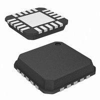
ISL54002IRTZ-T Intersil, ISL54002IRTZ-T Datasheet - Page 9

ISL54002IRTZ-T
Manufacturer Part Number
ISL54002IRTZ-T
Description
IC AMP AUDIO PWR 1.23W AB 20TQFN
Manufacturer
Intersil
Type
Class ABr
Datasheet
1.ISL54000IRTZ.pdf
(11 pages)
Specifications of ISL54002IRTZ-T
Output Type
2-Channel (Stereo)
Max Output Power X Channels @ Load
1.23W x 2 @ 8 Ohm
Voltage - Supply
2.7 V ~ 5.5 V
Features
Depop, Input Multiplexer, Shutdown, Thermal Protection
Mounting Type
Surface Mount
Package / Case
20-TQFN
Lead Free Status / RoHS Status
Lead free / RoHS Compliant
large copper pad and multiple vias to the GND plane. The
vias should be plugged and tented with plating and solder
mask to ensure good thermal conductivity.
Best thermal performance is achieved with the largest
practical copper ground plane area.
PCB Layout Considersations and Power
Supply Bypassing
To maintain the highest load dissipation and widest output
voltage swing the power supply PCB traces and the traces
that connect the output of the drivers to the speaker loads
should be made as wide as possible to minimize losses due
to parasitic trace resistance.
Typical Performance Curves
10.0
5.00
2.00
1.00
0.50
0.20
0.10
0.05
0.02
0.01
1.0
0.9
0.8
0.7
0.6
0.5
0.4
0.3
0.2
0.1
20
10m
V
BTL
R
P
V
BTL
R
f = 1kHz
DD
O
L
DD
L
FIGURE 3. THD+N vs OUTPUT POWER
= 8Ω
= 800mW
= 8Ω
FIGURE 1. THD+N vs FREQUENCY
= 5V
= 5V
50
20m
100
200
50m
OUTPUT POWER (W)
FREQUENCY (Hz)
9
500
100m
1k
200m
2k
T
A
ISL54000, ISL54001, ISL54002
= +25°C, Unless Otherwise Specified.
5k
500m
10k
1
20k
Proper supply bypassing is necessary for high power supply
rejection and low noise performance. A filter network
consisting of a 10µF capacitor in parallel with a 0.1µF
capacitor is recommended at the voltage regulator that is
providing the power to the ISL54000, ISL54001, and
ISL54002 IC.
Local bypass capacitors of 0.1µF should be put at each V
pin of the ISL54000, ISL54001, ISL54002 devices. They
should be located as close as possible to the pin, keeping
the length of leads and traces as short as possible.
A 1µF capacitor from the REF pin (pin 10) to GND is needed
for optimum PSRR and internal bias voltage stability.
1.0
0.9
0.8
0.7
0.6
0.5
0.4
0.3
0.2
0.1
10.0
5.00
2.00
1.00
0.50
0.20
0.10
0.05
0.02
0.01
20
10m
V
BTL
R
P
DD
L
O
V
BTL
R
f = 1kHz
= 8Ω
DD
L
= 200mW
= 3.6V
FIGURE 4. THD+N vs OUTPUT POWER
= 8Ω
50
= 3.6V
FIGURE 2. THD+N vs FREQUENCY
20m
100
200
40m
OUTPUT POWER (W)
FREQUENCY (Hz)
500
70m 100m
1k
2k
200m
5k
October 17, 2007
10k
FN6458.2
600m
20k
DD


