LM4928TLX/NOPB National Semiconductor, LM4928TLX/NOPB Datasheet - Page 13
LM4928TLX/NOPB
Manufacturer Part Number
LM4928TLX/NOPB
Description
IC AMP AUDIO PWR 2.2W AB 16USMD
Manufacturer
National Semiconductor
Series
Boomer®r
Type
Class ABr
Datasheet
1.LM4928TLNOPB.pdf
(20 pages)
Specifications of LM4928TLX/NOPB
Output Type
2-Channel (Stereo)
Max Output Power X Channels @ Load
2.2W x 2 @ 4 Ohm
Voltage - Supply
2.4 V ~ 5.5 V
Features
Depop, Differential Inputs, Shutdown, Thermal Protection
Mounting Type
Surface Mount
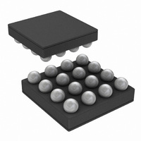
Package / Case
16-MicroSMD
Operational Class
Class-AB
Audio Amplifier Output Configuration
2-Channel Stereo
Output Power (typ)
1.5x2@8OhmW
Audio Amplifier Function
Speaker
Total Harmonic Distortion
0.04@8Ohm@1W%
Single Supply Voltage (typ)
3/5V
Dual Supply Voltage (typ)
Not RequiredV
Power Supply Requirement
Single
Rail/rail I/o Type
No
Power Supply Rejection Ratio
90dB
Single Supply Voltage (min)
2.4V
Single Supply Voltage (max)
5.5V
Dual Supply Voltage (min)
Not RequiredV
Dual Supply Voltage (max)
Not RequiredV
Operating Temp Range
-40C to 85C
Operating Temperature Classification
Industrial
Mounting
Surface Mount
Pin Count
16
Package Type
uSMD
For Use With
LM4928TLBD - BOARD EVALUATION LM4928TL
Lead Free Status / RoHS Status
Lead free / RoHS Compliant
Other names
LM4928TLX


Application Information
However, a direct consequence of the increased power de-
livered to the load by a bridge amplifier is an increase in
internal power dissipation versus a single-ended amplifier
operating at the same conditions.
Since the LM4928 has bridged outputs, the maximum inter-
nal power dissipation is 4 times that of a single-ended am-
plifier. Even with this substantial increase in power dissipa-
tion, the LM4928 does not require additional heatsinking
under most operating conditions and output loading. From
Equation 3, assuming a 5V power supply and an 8Ω load,
the maximum power dissipation point is 625mW per chan-
nel. Then multiply by two or use equation 4 to get 1.25W total
power dissipation for both channels. The maximum power
dissipation point obtained from Equation 4 must not be
greater than the power dissipation results from Equation 5:
Depending on the ambient temperature, T
surroundings, Equation 5 can be used to find the maximum
internal power dissipation supported by the IC packaging. If
the result of Equation 4 is greater than that of Equation 5,
then either the supply voltage must be decreased, the load
impedance increased, the ambient temperature reduced, or
the θ
traces near the output, V
lower the θ
heatsinking allowing higher power dissipation. For the typical
application of a 5V power supply, with an 8Ω load in the LLP
package, the maximum ambient temperature possible with-
out violating the maximum junction temperature is approxi-
mately 85˚C provided that device operation is around the
maximum power dissipation point. Recall that internal power
dissipation is a function of output power. If typical operation
is not around the maximum power dissipation point, the
LM4928 can operate at higher ambient temperatures. Refer
to the Typical Performance Characteristics curves for
power dissipation information.
POWER SUPPLY BYPASSING
As with any power amplifier, proper supply bypassing is
critical for low noise performance and high power supply
rejection ratio (PSRR). The capacitor location on both the
bypass and power supply pins should be as close to the
device as possible. A larger half-supply bypass capacitor
improves PSRR because it increases half-supply stability.
Typical applications employ a 5V regulator with 10µF and
0.1µF bypass capacitors that increase supply stability. This,
however, does not eliminate the need for bypassing the
supply nodes of the LM4928. The LM4928 will operate with-
out the bypass capacitor C
crease. A 1µF capacitor is recommended for C
maximizes PSRR performance. Lesser values may be used,
P
P
DMAX
DMAX
JA
reduced with heatsinking. In many cases, larger
P
= 8(V
JA
DMAX
= 4(V
. The larger areas of copper provide a form of
P
DD
DD
= (V
DMAX
)
)
2
2
/(2π
/(2π
DD
= (T
)
2
2
2
DD
R
R
/ (2π
L
L
, and GND pins can be used to
B
JMAX
) Bridge Mode both channel (4)
) Bridge Mode per channel (3)
, although the PSRR may de-
2
R
- T
L
) Single-Ended
A
) / θ
JA
(Continued)
A
, of the system
B
. This value
(2)
(5)
13
but PSRR decreases at frequencies below 1kHz. The issue
of C
click and pop performance.
OPTIMIZING RF IMMUNITY
The internal circuitry of the LM4928 suppresses the amount
of RF signal that is coupled into the chip. However, certain
external factors, such as output trace length, output trace
orientation, distance between the chip and the antenna,
antenna strength, speaker type, and type of RF signal, may
affect the RF immunity of the LM4928. In general, the RF
immunity of the LM4928 is application specific. Neverthe-
less, optimal RF immunity can be achieved by using short
output traces and increasing the distance between the
LM4928 and the antenna.
SHUTDOWN FUNCTION
In order to reduce power consumption while not in use, the
LM4928 contains shutdown circuitry that is used to turn off
the amplifier’s bias circuitry. The device may then be placed
into shutdown mode by toggling the Shutdown Select pin to
logic low. The trigger point for shutdown is shown as a typical
value in the Supply Current vs Shutdown Voltage graphs in
the Typical Performance Characteristics section. It is best
to switch between ground and supply for maximum perfor-
mance. While the device may be disabled with shutdown
voltages in between ground and supply, the idle current may
be greater than the typical value of 0.1µA. In either case, the
shutdown pin should be tied to a definite voltage to avoid
unwanted state changes.
In many applications, a microcontroller or microprocessor
output is used to control the shutdown circuitry, which pro-
vides a quick, smooth transition to shutdown. Another solu-
tion is to use a single-throw switch in conjunction with an
external pull-up resistor. This scheme guarantees that the
shutdown pin will not float, thus preventing unwanted state
changes.
PROPER SELECTION OF EXTERNAL COMPONENTS
Proper selection of external components in applications us-
ing integrated power amplifiers is critical when optimizing
device and system performance. Although the LM4928 is
tolerant to a variety of external component combinations,
consideration of component values must be made when
maximizing overall system quality.
The LM4928 is unity-gain stable, giving the designer maxi-
mum system flexibility. The LM4928 should be used in low
closed-loop gain configurations to minimize THD+N values
and maximize signal to noise ratio. Low gain configurations
require large input signals to obtain a given output power.
Input signals equal to or greater than 1Vrms are available
from sources such as audio codecs. Please refer to the
Audio Power Amplifier Design section for a more complete
explanation of proper gain selection. When used in its typical
application as a fully differential power amplifier the LM4928
does not require input coupling capacitors for input sources
with DC common-mode voltages of less than V
allowable input common-mode voltage levels are actually a
function of V
Equation 6:
B
selection is thus dependant upon desired PSRR and
V
CMi
DD
<
, R
(V
i
DD
, and R
-1.2)(R
f
i
+R
and may be determined by
f
)/R
f
-V
DD
/2(R
i
/R
www.national.com
f
)
DD
. Exact
(6)
Related parts for LM4928TLX/NOPB
Image
Part Number
Description
Manufacturer
Datasheet
Request
R

Part Number:
Description:
1.2 Watt Stereo Fully Differential Audio Amplifier With Rf Suppression And Shutdown Low
Manufacturer:
National Semiconductor Corporation
Datasheet:

Part Number:
Description:
Manufacturer:
National Semiconductor
Datasheet:

Part Number:
Description:
IC AMP AUDIO PWR 2.2W AB 16USMD
Manufacturer:
National Semiconductor
Datasheet:
Part Number:
Description:
National Semiconductor [8-Bit D/A Converter]
Manufacturer:
National Semiconductor
Datasheet:
Part Number:
Description:
National Semiconductor [Media Coprocessor]
Manufacturer:
National Semiconductor
Datasheet:
Part Number:
Description:
Digitally Controlled Tone and Volume Circuit with Stereo Audio Power Amplifier, Microphone Preamp Stage and National 3D Sound
Manufacturer:
National Semiconductor
Datasheet:
Part Number:
Description:
Digitally Controlled Tone and Volume Circuit with Stereo Audio Power Amplifier, Microphone Preamp Stage and National 3D Sound
Manufacturer:
National Semiconductor
Datasheet:
Part Number:
Description:
AC97 Rev 2 Codec with Sample Rate Conversion and National 3D Sound
Manufacturer:
National Semiconductor
Part Number:
Description:
Manufacturer:
National Semiconductor
Datasheet:
Part Number:
Description:
Manufacturer:
National Semiconductor
Datasheet:
Part Number:
Description:
General Purpose, Low Voltage, Low Power, Rail-to-Rail Output Operational Amplifiers
Manufacturer:
National Semiconductor
Datasheet:
Part Number:
Description:
8-bit 20 MSPS flash A/D converter.
Manufacturer:
National Semiconductor
Datasheet:
Part Number:
Description:
Low Noise Quad Operational Amplifier
Manufacturer:
National Semiconductor
Datasheet:
Part Number:
Description:
Quad Differential Line Receivers
Manufacturer:
National Semiconductor
Datasheet: