LM4898ITL/NOPB National Semiconductor, LM4898ITL/NOPB Datasheet - Page 14
LM4898ITL/NOPB
Manufacturer Part Number
LM4898ITL/NOPB
Description
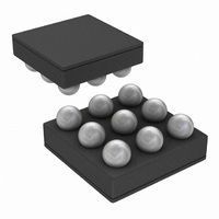
IC AMP AUDIO PWR 1.4W MONO 9USMD
Manufacturer
National Semiconductor
Series
Boomer®r
Type
Class ABr
Datasheet
1.LM4898LDNOPB.pdf
(17 pages)
Specifications of LM4898ITL/NOPB
Output Type
1-Channel (Mono)
Max Output Power X Channels @ Load
1.4W x 1 @ 4 Ohm
Voltage - Supply
2.4 V ~ 5.5 V
Features
Depop, Differential Inputs, Shutdown, Thermal Protection
Mounting Type
Surface Mount
Package / Case
9-MicroSMD
Operational Class
Class-AB
Audio Amplifier Output Configuration
1-Channel Mono
Output Power (typ)
1x1@8OhmW
Audio Amplifier Function
Speaker
Total Harmonic Distortion
0.05@8Ohm@400mW%
Single Supply Voltage (typ)
3/5V
Dual Supply Voltage (typ)
Not RequiredV
Power Supply Requirement
Single
Rail/rail I/o Type
No
Power Supply Rejection Ratio
90dB
Single Supply Voltage (min)
2.4V
Single Supply Voltage (max)
5.5V
Dual Supply Voltage (min)
Not RequiredV
Dual Supply Voltage (max)
Not RequiredV
Operating Temp Range
-40C to 85C
Operating Temperature Classification
Industrial
Mounting
Surface Mount
Pin Count
9
Package Type
uSMD
For Use With
LM4898ITLBD - BOARD EVALUATION LM4898ITL
Lead Free Status / RoHS Status
Lead free / RoHS Compliant
Other names
LM4898ITL
LM4898ITL
LM4898ITL


www.national.com
Application Information
AUDIO POWER AMPLIFIER DESIGN
Design a 1W/8Ω Audio Amplifier
Given:
A designer must first determine the minimum supply rail to
obtain the specified output power. The supply rail can easily
be found by extrapolating from the Output Power vs. Supply
Voltage graphs in the Typical Performance Characteristics
section. A second way to determine the minimum supply rail
is to calculate the required Vopeak using Equation 7 and add
the dropout voltages. Using this method, the minimum sup-
ply voltage is (Vopeak +(V
BOT
vs. Supply Voltage curve in the Typical Performance Char-
acteristics section.
Using the Output Power vs. Supply Voltage graph for an 8Ω
load, the minimum supply rail just about 5V. Extra supply
voltage creates headroom that allows the LM4898 to repro-
• Power Output
• Load Impedance
• Input Level
• Input Impedance
• Bandwidth
and V
DO TOP
are extrapolated from the Dropout Voltage
DO TOP
+(V
100Hz–20kHz
DO BOT
(Continued)
)),where V
±
0.25dB
1Vrms
20kΩ
1W
8Ω
(7)
DO
14
duce peaks in excess of 1W without producing audible dis-
tortion. At this time, the designer must make sure that the
power supply choice along with the output impedance does
not violate the conditions explained in the Power Dissipation
section. Once the power dissipation equations have been
addressed, the required differential gain can be determined
from Equation 8.
R
From Equation 8, the minimum A
sired input impedance was 20kΩ, a ratio of 2.83:1 of R
results in an allocation of R
and R
step is to address the bandwidth requirement which must be
stated as a single -3dB frequency point. Five times away
from a -3dB point is 0.17dB down from passband response
which is better than the required
f
The high frequency pole is determined by the product of the
desired frequency pole, f
.With a A
150kHz which is much smaller than the LM4898 GBWP of
10MHz. This figure displays that if a designer has a need to
design an amplifier with a higher differential gain, the
LM4898 can still be used without running into bandwidth
limitations.
H
f
= 20kHz * 5 =100kHz
/ R
i
f
= 60kΩ for both feedback resistors. The final design
= A
VD
VD
= 2.83 and f
H
H
= 100kHz, the resulting GBWP =
i
, and the differential gain, A
= 20kΩ for both input resistors
±
VD
0.25dB specified.
is 2.83. Since the de-
f
to R
(8)
VD
i
Related parts for LM4898ITL/NOPB
Image
Part Number
Description
Manufacturer
Datasheet
Request
R

Part Number:
Description:
Manufacturer:
National Semiconductor
Datasheet:
Part Number:
Description:
National Semiconductor [8-Bit D/A Converter]
Manufacturer:
National Semiconductor
Datasheet:
Part Number:
Description:
National Semiconductor [Media Coprocessor]
Manufacturer:
National Semiconductor
Datasheet:
Part Number:
Description:
Digitally Controlled Tone and Volume Circuit with Stereo Audio Power Amplifier, Microphone Preamp Stage and National 3D Sound
Manufacturer:
National Semiconductor
Datasheet:
Part Number:
Description:
Digitally Controlled Tone and Volume Circuit with Stereo Audio Power Amplifier, Microphone Preamp Stage and National 3D Sound
Manufacturer:
National Semiconductor
Datasheet:
Part Number:
Description:
AC97 Rev 2 Codec with Sample Rate Conversion and National 3D Sound
Manufacturer:
National Semiconductor
Part Number:
Description:
Manufacturer:
National Semiconductor
Datasheet:
Part Number:
Description:
Manufacturer:
National Semiconductor
Datasheet:
Part Number:
Description:
General Purpose, Low Voltage, Low Power, Rail-to-Rail Output Operational Amplifiers
Manufacturer:
National Semiconductor
Datasheet:
Part Number:
Description:
8-bit 20 MSPS flash A/D converter.
Manufacturer:
National Semiconductor
Datasheet:
Part Number:
Description:
Low Noise Quad Operational Amplifier
Manufacturer:
National Semiconductor
Datasheet:
Part Number:
Description:
Quad Differential Line Receivers
Manufacturer:
National Semiconductor
Datasheet:
Part Number:
Description:
Quad High Speed Trapezoidal? Bus Transceiver
Manufacturer:
National Semiconductor
Datasheet:
Part Number:
Description:
Dual Line Receiver
Manufacturer:
National Semiconductor
Datasheet: