JC1AF-DC48V-TV-F Panasonic Electric Works, JC1AF-DC48V-TV-F Datasheet
JC1AF-DC48V-TV-F
Specifications of JC1AF-DC48V-TV-F


Related parts for JC1AF-DC48V-TV-F


JC1AF-DC48V-TV-F Summary of contents
Page 1
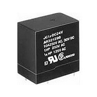
... Half-wave pulse of sine wave: 6ms * 6 Detection time: 10µs * Refer to 6. Conditions for operation, transport and storage mentioned in 7 AMBIENT ENVIRONMENT All Rights Reserved © COPYRIGHT Panasonic Electric Works Co., Ltd. COMPACT POWER RELAYS FEATURES • High inrush current capability 30.0 19.0 1.181 .748 ...
Page 2
... DIA. .020 .020 1 15.2 .598 30 2 1.181 7.6 .299 3 10 3.1 .122 19 General tolerance: ±0.3 All Rights Reserved © COPYRIGHT Panasonic Electric Works Co., Ltd. TM DC12V Coil voltage 12, 24 Nominal Nominal operating operating current, power 150 0.9 75 0.9 37.5 0.9 18.8 ...
Page 3
... AC resistive load inductive load DC resistive load (cosϕ inductive load (L ms) 0 100 400 Contact voltage, V All Rights Reserved © COPYRIGHT Panasonic Electric Works Co., Ltd 1.772 1.4 DIA. .055 8.35 8.35 .329 .329 2.5 0.5 2.5 .098 .020 .098 4.75 Accept Faston 187 ...
Page 4
... Contact current, A 3.-(3) Coil temperature rise Point measured: Inside the coil Ambient temperature: 60°C 140° 100 110 120 130 140 Coil applied voltage, %V All Rights Reserved © COPYRIGHT Panasonic Electric Works Co., Ltd. 4. Operate / release time Operate time Max. ...