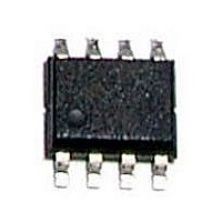
BH3547F-E2 Rohm Semiconductor, BH3547F-E2 Datasheet - Page 7

BH3547F-E2
Manufacturer Part Number
BH3547F-E2
Description
IC AMP STEREO HEADPHONE 8SOP
Manufacturer
Rohm Semiconductor
Type
Class ABr
Specifications of BH3547F-E2
Output Type
Headphones, 2-Channel (Stereo)
Max Output Power X Channels @ Load
77mW x 2 @ 16 Ohm
Voltage - Supply
4.5 V ~ 5.5 V
Features
Mute, Thermal Protection
Mounting Type
Surface Mount
Package / Case
8-SOP
No. Of Channels
2
Supply Voltage Range
4.5V To 6.5V
Thd + N
0.05% @ 32ohm, VDD=5V
Load Impedance
16ohm
Operating Temperature Range
-25°C To +75°C
Amplifier Case Style
SOIC
No. Of Pins
8
Rohs Compliant
Yes
Lead Free Status / RoHS Status
Lead free / RoHS Compliant
Available stocks
Company
Part Number
Manufacturer
Quantity
Price
Company:
Part Number:
BH3547F-E2
Manufacturer:
ROHM
Quantity:
2 500
Company:
Part Number:
BH3547F-E2
Manufacturer:
ROHM
Quantity:
2 500
Company:
Part Number:
BH3547F-E2
Manufacturer:
PULSE
Quantity:
40 000
Part Number:
BH3547F-E2
Manufacturer:
ROHM/罗姆
Quantity:
20 000
© 2010 ROHM Co., Ltd. All rights reserved.
BH3541F,BH3544F,BH3547F,BH3548F
www.rohm.com
4) GND potential
5) Thermal design
6) Shorts between pins and misinstallation
7) Operation in strong magnetic fields
8) Pop noise countermeasures
1)BH3541F/ BH3544F/ BH3548F
2)BH3547F
Make the GND pin voltage such that it is the lowest voltage even when operating below it. Actually confirm that the
voltage of each pin does not become a lower voltage than the GND pin, including transient phenomena.
Perform thermal design in which there are adequate margins by taking into account the allowable power dissipation in
actual states of use.
When mounting the LSI on a board, pay adequate attention to orientation and placement discrepancies of the LSI.
If it is misinstalled and the power is turned on, the LSI may be damaged. It also may be damaged if it is shorted by a
foreign substance coming between pins of the LSI or between a pin and a power supply or a pin and a GND.
Adequately evaluate use in a strong magnetic field, since there is a possibility of malfunction.
In order to prevent the pop noise that occurs when the power supply turns ON or OFF, make the rise and fall with
reference to the timing diagram shown below.
(A):Mute period (Use as pop noise countermeasure when power supply turns ON/OFF by makingVMUTE=Lo.)
(B):Mute cancellation period (This has a time constant because it is used by the externally attached C2 and R2 as
(C):Mute start time (As on cancellation, this has a time constant.)
(A):Before VCC rise (or at the same time as VCC) make mute cancelled (VMUTE=Hi).
(B):Soft mute period (This time can be set by externally attached R2 and C2)
a pop noise countermeasure on mute cancellation, so be careful of the timing.)
(A)
MUTE
Vmute
OUT
VCC
SG
(Input Signal)
VCC
OUT
(Rise time)
Rise time
A
PLAY period
B
(PLAY period)
Fig. 16
Fig. 17
7/8
(B)
C
A
Rise time
(MUTE period)
(Fall period)
Technical Note
2010.05 - Rev.A


