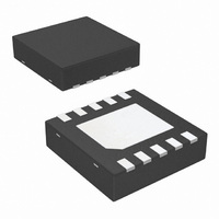
LM4980SD/NOPB National Semiconductor, LM4980SD/NOPB Datasheet - Page 13

LM4980SD/NOPB
Manufacturer Part Number
LM4980SD/NOPB
Description
IC AMP AUDIO .042W STER AB 10LLP
Manufacturer
National Semiconductor
Series
Boomer®, PowerWise®r
Type
Class ABr
Datasheet
1.LM4980SDNOPB.pdf
(20 pages)
Specifications of LM4980SD/NOPB
Output Type
Headphones, 2-Channel (Stereo)
Max Output Power X Channels @ Load
42mW x 2 @ 16 Ohm
Voltage - Supply
1.5 V ~ 3.3 V
Features
Depop, Shutdown, Thermal Protection
Mounting Type
Surface Mount
Package / Case
10-LLP
Lead Free Status / RoHS Status
Lead free / RoHS Compliant
Other names
LM4980SD
LM4980SDTR
LM4980SDTR
Application Information
AMPLIFIER CONFIGURATION
As shown in Figure 1, the LM4980 consists of a stereo pair
of audio amplifiers. These amplifiers operate on a single
supply and have single-ended inputs and outputs. The qui-
escent operating point of each amplifier input and output is
equal to the voltage applied to the V
C
Careful consideration should be paid to value of C
the capacitor connected between the MIDCAP pin and
ground. The value of C
LM4980 settles to quiescent operation and determines the
amount of output transient suppression. Choosing C
equal to 4.7µF along with a small value of C
of 0.1µF to 1.0µF), produces shutdown function that is es-
sentially output-transient free. Choosing C
necessary for the desired bandwidth helps minimize clicks
and pops. This ensures that output transients are minimized
when power is first applied or the LM4980 resumes opera-
tion after shutdown. The MIDCAP offers the following ben-
efits: better linearity for reduced THD+N, reduced channel-
to-channel crosstalk, and less susceptibility to ground noise.
For the ultimate suppression of output transient when power
is applied or removed, ensure that the voltage applied to the
SHDN pin is a logic low. This will activate the micro-power
shutdown.
OPTIMIZING OUTPUT-GROUND NOISE REDUCTION
In addition to the output-ground noise reduction afforded by
C
of a ferrite bead. The ferrite bead (FB) is placed between
ground and common connection between the C
the headphone ground connection. This is shown in Figure
3. The ferrite bead is beneficial in environments where the
headphone and C
circuitry (such as video) that may inject noise on a common
ground.
OPTIMIZING OUTPUT TRANSIENT SUPPRESSION
The LM4980 contains circuitry that eliminates turn-on and
shutdown output transients ("clicks and pops"). For this dis-
cussion, turn-on refers to either applying the power supply
voltage or when the micro-power shutdown mode is deacti-
vated. The turn-on time delay is the time duration that occurs
between the application of the power supply voltage or de-
activating shutdown and when the applied input signal ap-
pears at the amplifier outputs.
C
output transients. The amount of suppression increases as
MIDCAP
MIDCAP
MIDCAP
FIGURE 3. Adding a ferrite bead improves
, further reduction can be achieved by the inclusion
’s value plays a significant role in the suppression of
VALUE SELECTION
ground-noise suppression
MIDCAP
MIDCAP
ground connection is shared with
determines how fast the
MID
pin (usually V
IN
IN
no larger than
(in the range
MIDCAP
20142981
MIDCAP
MIDCAP
DD
and
/2).
,
13
C
C
relationship between the value of C
time. Here are some typical turn-on times for various values
of C
STAND-ALONE V
The LM4980 is designed to take advantage of audio DACs
(digital-to-analog converters) and other signal sources that,
in addition to generating an analog signal, also create an AC
ground potential. This AC ground potential is typically V
This V
Using two external resistors allows the LM4980 to be easily
used in applications where the V
generated and supplied to the LM4980 by other circuits.
Figure 4 shows this configuration.
SELECTING THE OUTPUT COUPLING CAPACITOR
VALUE
To ensure that no performance degrading DC current flows
through the load (something with which speakers would just
as soon not have to tolerate), coupling capacitors are nec-
essary between the amplifier output pins and the load. Be-
sides blocking DC current, the output coupling capacitor
value, together with the load resistance, produces a low
frequency amplitude rolloff, whose cutoff frequency is found
using Equation 1.
When driving 32Ω headphones, the 220µF C
pacitors shown in Figure 2 produce a cutoff frequency equal
to 23Hz.
The output coupling capacitors also influence the output
transient behavior at power-up and when activating or deac-
MIDCAP
MIDCAP
TABLE 1. Typical turn-on time versus C
FIGURE 4. Simple circuit generates LM4980’s V
MIDCAP
C
MIDCAP
DD
’s value increases. However, changing the value of
/2 is applied to the LM4980’s V
alters the LM4980’s turn-on time. There is a linear
.
10.0
VALUE (µF)
4.7
6.8
MID
VOLTAGE GENERATION
voltage
MID
Turn-On Time (ms)
MIDCAP
voltage is not internally
MID
20142980
250
360
530
and the turn-on
MIDCAP
pin (pin 4).
COUPLING
www.national.com
value
MID
DD
ca-
(1)
/2.


