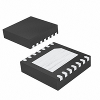
MAX9814ETD+T Maxim Integrated Products, MAX9814ETD+T Datasheet - Page 9

MAX9814ETD+T
Manufacturer Part Number
MAX9814ETD+T
Description
IC AMP AUDIO MONO AB MIC 14TDFN
Manufacturer
Maxim Integrated Products
Type
Class ABr
Datasheet
1.MAX9814ETDT.pdf
(14 pages)
Specifications of MAX9814ETD+T
Output Type
1-Channel (Mono)
Voltage - Supply
2.7 V ~ 5.5 V
Features
AGC, Microphone, Shutdown
Mounting Type
Surface Mount
Package / Case
14-TDFN Exposed Pad
Product
General Purpose Audio Amplifiers
Thd Plus Noise
0.04 %
Operating Supply Voltage
2.7 V to 5.5 V
Supply Current
3.1 mA
Maximum Power Dissipation
1481 mW
Maximum Operating Temperature
+ 85 C
Mounting Style
SMD/SMT
Minimum Operating Temperature
- 40 C
Supply Voltage (max)
5.5 V
Supply Voltage (min)
2.7 V
Amplifier Class
AB
No. Of Channels
1
Supply Voltage Range
2.7V To 5.5V
Load Impedance
50ohm
Operating Temperature Range
-40°C To +85°C
Amplifier Case Style
TDFN
No. Of Pins
14
Rohs Compliant
Yes
Lead Free Status / RoHS Status
Lead free / RoHS Compliant
Max Output Power X Channels @ Load
-
Lead Free Status / Rohs Status
Lead free / RoHS Compliant
Other names
MAX9814ETD+T
MAX9814ETD+TTR
MAX9814ETD+TTR
To set the output-voltage threshold at which the micro-
phone output is clamped, an external resistor-divider
must be connected from MICBIAS to ground with the out-
put of the resistor-divider applied to TH. The voltage V
determines the peak output-voltage threshold at which
the output becomes clamped. The maximum signal
swing at the output is then limited to two times V
remains at that level until the amplitude of the input signal
is reduced. To disable AGC, connect TH to MICBIAS.
MICBIAS is capable of sourcing 20mA. Select a value for
R
electret microphone. A value of 2.2kΩ is usually sufficient
for a microphone of typical sensitivity. Consult the micro-
phone data sheet for the recommended bias resistor.
The BIAS output of the MAX9814 is internally buffered
and provides a low-noise bias. Bypass BIAS with a
470nF capacitor to ground.
The input AC-coupling capacitor (C
resistance (R
highpass filter that removes any DC bias from an input
signal (see the Typical Application Circuit/Functional
Diagram ). C
input-signal source from appearing at the amplifier out-
puts. The -3dB point of the highpass filter, assuming
zero source impedance due to the input signal source,
is given by:
MICBIAS
that provides the desired bias current for the
IN
IN
prevents any DC components from the
f
−
) to the microphone amplifier form a
3dB_IN
_______________________________________________________________________________________
Setting the AGC Threshold
Microphone Bias Resistor
=
2
π
×
Microphone Amplifier with AGC and
R
IN
1
×
Input Capacitor
C
Bias Capacitor
IN
IN
) and the input
TH
Low-Noise Microphone Bias
and
TH
Choose C
frequency of interest. Setting f
amplifier’s low-frequency response. Use capacitors with
low-voltage coefficient dielectrics. Aluminum electrolytic,
tantalum, or film dielectric capacitors are good choices
for AC-coupling capacitors. Capacitors with high-voltage
coefficients, such as ceramics (non-C0G dielectrics), can
result in increased distortion at low frequencies.
The output of the MAX9814 is biased at 1.23V. To elimi-
nate the DC offset, an AC-coupling capacitor (C
must be used. Depending on the input resistance (R
of the following stage, C
highpass filter. The -3dB point of the highpass filter,
assuming zero output impedance, is given by:
The MAX9814 features a low-power shutdown mode.
When SHDN goes low, the supply current drops to
0.01µA, the output enters a high-impedance state, and
the bias current to the microphone is switched off.
Driving SHDN high enables the amplifier. Do not leave
SHDN unconnected.
Bypass the power supply with a 0.1µF capacitor to
ground. Reduce stray capacitance by minimizing trace
lengths and place external components as close to the
device as possible. Surface-mount components are
recommended. In systems where analog and digital
grounds are available, connect the MAX9814 to analog
ground.
IN
such that f
f
−
3dB_OUT
-3dB_IN
Power-Supply Bypassing
=
OUT
2
π
-3dB_IN
×
and R
R
is well below the lowest
L
Output Capacitor
1
×
and PCB Layout
C
L
too high affects the
OUT
effectively form a
Shutdown
OUT
L
9
)
)


