LMV1088RL/NOPB National Semiconductor, LMV1088RL/NOPB Datasheet - Page 6
LMV1088RL/NOPB
Manufacturer Part Number
LMV1088RL/NOPB
Description
IC AMP AUDIO MONO AB MIC 36USMD
Manufacturer
National Semiconductor
Series
PowerWise®r
Type
Class ABr
Datasheet
1.LMV1088RLNOPB.pdf
(26 pages)
Specifications of LMV1088RL/NOPB
Output Type
1-Channel (Mono)
Voltage - Supply
2.7 V ~ 5.5 V
Features
Differential Inputs, I²C, Microphone, Mute
Mounting Type
Surface Mount
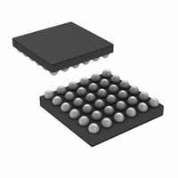
Package / Case
36-MicroSMDxt
Amplifier Class
AB
No. Of Channels
2
Supply Voltage Range
2.7V To 5.5V
Load Impedance
10kohm
Operating Temperature Range
-40°C To +85°C
Amplifier Case Style
SMD
No. Of Pins
36
Rohs Compliant
Yes
Lead Free Status / RoHS Status
Lead free / RoHS Compliant
Max Output Power X Channels @ Load
-
Other names
LMV1088RLTR


www.national.com
I
Symbol
DDCP
Digital Interface Characteristics
Unless otherwise specified, all limits guaranteed for T
Note 4: “Absolute Maximum Ratings” indicate limits beyond which damage to the device may occur, including inoperability and degradation of device reliability
and/or performance. Functional operation of the device and/or non-degradation at the Absolute Maximum Ratings or other conditions beyond those indicated in
the Recommended Operating Conditions is not implied. The Recommended Operating Conditions indicate conditions at which the device is functional and the
device should not be operated beyond such conditions. All voltages are measured with respect to the ground pin, unless otherwise specified.
Note 5: The Electrical Characteristics tables list guaranteed specifications under the listed Recommended Operating Conditions except as otherwise modified
or specified by the Electrical Characteristics Conditions and/or Notes. Typical specifications are estimations only and are not guaranteed.
Note 6: The maximum power dissipation must be de-rated at elevated temperatures and is dictated by T
allowable power dissipation is P
150°C and the typical θ
information.
Note 7: Human body model, applicable std. JESD22-A114C.
Note 8: Machine model, applicable std. JESD22-A115-A.
Note 9: Typical values represent most likely parametric norms at T
characterization and are not guaranteed.
Note 10: Datasheet min/max specification limits are guaranteed by test, or statistical analysis.
Note 11: In Pass Through mode, only one microphone input is active. See also I
Note 12: In Noise Canceling Mode there is 2.5dB additional gain before calibration when compared to the other operating modes to compensate for the gain
reduction that is caused by the noise canceling effect.
Note 13: The voltage at I
I
DD
th
ts
th
ts
V
V
CAL
PEC
PEC
CAL
IH
IL
Supply Current during Calibration and
Programming
Supply Current
Logic High Input Level
Logic Low Input Level
CAL Setup Time
CAL Hold time until calibration is
finished
PE Setup Time
PE Hold until calibration is finished
JA
2
for this microSMD package is 70°C/W and for the LLP package θ
CV
DD
Parameter
DMAX
must not exceed the voltage on V
= (T
JMAX
–T
A
)/ θ
JA
or the number given in the Absolute Maximum Ratings, whichever is lower. For the LMV1088, T
SCL, SDA, ADR, CAL, PE pins
SCL, SDA, ADR, CAL, PE pins
Calibrating or Programming EEPROM
V
mode
DD
IN
J
A
= 25°C, I
.
= +25°C, and at the Recommended Operation Conditions at the time of product
= 25mV
(Notes 4, 13)
P-P
6
2
CV
Conditions
2
C Compatible Interface for more information how to configure the LMV1088.
both inputs, Noise canceling
DD
within the Operating Rating (Note 13)
JA
is 64°C/W Refer to the Thermal Considerations section for more
JMAX
, θ
JC
, and the ambient temperature T
(Note 9)
Typical
2
2
28
1
LMV1088
0.6xI
0.4xI
(Note 10)
Limits
770
770
1.5
50
2
2
CV
CV
DD
DD
A
. The maximum
mA (max)
mA (max)
ms (min)
ms (min)
(Limits)
V (max)
V (min)
Units
JMAX
ms
ms
=
Related parts for LMV1088RL/NOPB
Image
Part Number
Description
Manufacturer
Datasheet
Request
R

Part Number:
Description:
Manufacturer:
National Semiconductor
Datasheet:
Part Number:
Description:
National Semiconductor [8-Bit D/A Converter]
Manufacturer:
National Semiconductor
Datasheet:
Part Number:
Description:
National Semiconductor [Media Coprocessor]
Manufacturer:
National Semiconductor
Datasheet:
Part Number:
Description:
Digitally Controlled Tone and Volume Circuit with Stereo Audio Power Amplifier, Microphone Preamp Stage and National 3D Sound
Manufacturer:
National Semiconductor
Datasheet:
Part Number:
Description:
Digitally Controlled Tone and Volume Circuit with Stereo Audio Power Amplifier, Microphone Preamp Stage and National 3D Sound
Manufacturer:
National Semiconductor
Datasheet:
Part Number:
Description:
AC97 Rev 2 Codec with Sample Rate Conversion and National 3D Sound
Manufacturer:
National Semiconductor
Part Number:
Description:
Manufacturer:
National Semiconductor
Datasheet:
Part Number:
Description:
Manufacturer:
National Semiconductor
Datasheet:
Part Number:
Description:
General Purpose, Low Voltage, Low Power, Rail-to-Rail Output Operational Amplifiers
Manufacturer:
National Semiconductor
Datasheet:
Part Number:
Description:
8-bit 20 MSPS flash A/D converter.
Manufacturer:
National Semiconductor
Datasheet:
Part Number:
Description:
Low Noise Quad Operational Amplifier
Manufacturer:
National Semiconductor
Datasheet:
Part Number:
Description:
Quad Differential Line Receivers
Manufacturer:
National Semiconductor
Datasheet:
Part Number:
Description:
Quad High Speed Trapezoidal? Bus Transceiver
Manufacturer:
National Semiconductor
Datasheet:
Part Number:
Description:
Dual Line Receiver
Manufacturer:
National Semiconductor
Datasheet: