ISD5116EY Nuvoton Technology Corporation of America, ISD5116EY Datasheet - Page 25
ISD5116EY
Manufacturer Part Number
ISD5116EY
Description
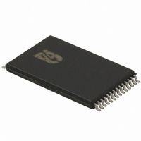
IC VOICE REC/PLAY 8-16MN 28-TSOP
Manufacturer
Nuvoton Technology Corporation of America
Series
ISD5100r
Datasheet
1.ISD5116SY.pdf
(90 pages)
Specifications of ISD5116EY
Interface
I²C
Filter Pass Band
1.7 ~ 3.4kHz
Duration
8 ~ 16 Min
Mounting Type
Surface Mount
Package / Case
28-TSOP
For Use With
ISD-ES511 - EVALUATION SYSTEM FOR ISD5100ISD-ES501 - EVALUATION SYSTEM FOR ISD5008
Lead Free Status / RoHS Status
Lead free / RoHS Compliant
Available stocks
Company
Part Number
Manufacturer
Quantity
Price
Company:

Part Number:
ISD5116EY
Manufacturer:
IDT
Quantity:
287


In this mode, the elements of the original PASS THROUGH mode do not change. The sections of the
chip not required to add the record path remain powered down. In fact, CFG0 does not change and
remains
CFG1 changes to
Since CFG0 is not changed, it is only necessary to load CFG1. Note that if only CFG0 was changed, it
would be necessary to load both registers.
The Memo Record mode sets the chip up to record from the local microphone into the chip’s Multilevel
Storage Array. A connected cellular telephone or cordless phone chip set may remain powered down
and is not active in this mode. The path to be used is microphone input to AGC amplifier, then through
the INPUT SOURCE MUX to the SUM1 SUMMING amplifier. From there the path goes through the
FILTER MUX, the LOW PASS FILTER, the SUM2 SUMMING amplifier, then to the MULTILEVEL
STORAGE ARRAY. In this instance, we will select the 5.3 kHz sample rate. The rest of the chip may
be powered down.
3. Select the SUM1 SUMMING amplifier path through the FILTER MUX—Bit FLS0 controls the
4. Power up the LOW PASS FILTER—Bit FLPD controls the power up state of the LOW PASS
5. Select the 6.4 kHz sample rate — Bits FLD0 and FLD1 select the Low Pass filter setting and
6. Select the LOW PASS FILTER input (only) to the S2 SUMMING amplifier — Bits S2M0 and
1. Power up the AGC amplifier—Bit AGPD controls the power up state of the AGC amplifier. This
2. Select the AGC amplifier through the INPUT SOURCE MUX—Bit INS0 controls the state of
3. Select the INPUT SOURCE MUX (only) to the S1 SUMMING amplifier — Bits S1M0 and S1M1
CFG0=0100 0100 0000 1011 (hex 440B).
CFG1=0000 0000 1100 0101 (hex 00C5).
state of the FILTER MUX. This is bit D4 of CFG1 and it must be set to ZERO to select the
SUM1 SUMMING amplifier path.
FILTER stage. This is bit D1 of CFG1 and it must be set to ZERO to power up the LOW PASS
FILTER STAGE.
sample rate to be used during record and playback. These are bits D2 and D3 of CFG1. To
enable the 6.4 kHz sample rate, D2 must be set to ONE and D3 set to ZERO.
S2M1 control the state of the SUM2 SUMMING amplifier. These are bits D5 and D6
respectively of CFG1 and they should be set to the state where D5 is ZERO and D6 is ONE to
select the LOW PASS FILTER (only) path.
6.3.9
is bit D0 of CFG1 and must be set to ZERO to power up this stage.
the INPUT SOURCE MUX. This is bit D9 of CFG0 and must be set to a ZERO to select the
AGC amplifier.
control the state of the SUM1 SUMMING amplifier. These are bits D7 and D8 respectively of
CFG1 and they should be set to the state where D7 is ZERO and D8 is ONE to select the
INPUT SOURCE MUX (only) path.
Memo Record
- 25 -
Publication Release Date: Oct 31, 2008
ISD5100 SERIES
Revision 1.42
Related parts for ISD5116EY
Image
Part Number
Description
Manufacturer
Datasheet
Request
R

Part Number:
Description:
MODULE FOR VOICE REC/PLAY 10S
Manufacturer:
Nuvoton Technology Corporation of America
Part Number:
Description:
Manufacturer:
Nuvoton Technology Corporation of America
Datasheet:
Part Number:
Description:
Manufacturer:
Nuvoton Technology Corporation of America
Datasheet:
Part Number:
Description:
Manufacturer:
Nuvoton Technology Corporation of America
Datasheet:
Part Number:
Description:
Manufacturer:
Nuvoton Technology Corporation of America
Datasheet:
Part Number:
Description:
Manufacturer:
Nuvoton Technology Corporation of America
Datasheet:
Part Number:
Description:
Manufacturer:
Nuvoton Technology Corporation of America
Datasheet: