DS2180AQN+T&R Maxim Integrated Products, DS2180AQN+T&R Datasheet - Page 2
DS2180AQN+T&R
Manufacturer Part Number
DS2180AQN+T&R
Description
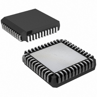
IC TRANSCEIVER T1 44-PLCC
Manufacturer
Maxim Integrated Products
Datasheet
1.DS2180A.pdf
(35 pages)
Specifications of DS2180AQN+T&R
Function
Transceiver
Interface
T1
Number Of Circuits
1
Voltage - Supply
4.5 V ~ 5.5 V
Current - Supply
3mA
Operating Temperature
-40°C ~ 85°C
Mounting Type
Surface Mount
Package / Case
44-LCC, 44-PLCC
Includes
Alarm Generation and Detection, B7 Stuffing Mode, B8ZS Mode, Error Detection and Counter, "Hardware" Mode, Transparent Mode
Lead Free Status / RoHS Status
Lead free / RoHS Compliant
Power (watts)
-


DS1386/DS1386P
DESCRIPTION
The DS2180A is a monolithic CMOS device designed to implement primary rate (1.544 MHz) T-carrier
transmission systems. The 193S framing mode is intended to support existing Ft/Fs applications (12
frames/superframe).
The 193E framing mode supports the extended superframe format (24
frames/superframe). Clear channel capability is provided by selection of appropriate zero suppression
and signaling modes.
Several functional blocks exist in the transceiver. The transmit framer/formatter generates appropriate
framing bits, inserts robbed bit signaling, supervises zero suppression, generates alarms, and provides
output clocks useful for data conditioning and decoding. The receive synchronizer establishes frame and
multi-frame boundaries by identifying frame signaling bits, extracts signaling data, reports alarms and
transmission errors, and provides output clocks useful for data conditioning and decoding.
The control block is shared between transmit and receive sides. This block determines the frame, zero
suppression, alarm and signaling formats. User access to the control block is by one of two modes.
In the processor mode, pins 14 through 18 are a micro-processor/ microcontroller-compatible serial port
which can be used for device configuration, control and status monitoring.
In the hardware mode, no offboard processor is required. Pins 14 through 18 are reconfigured into “hard-
wired” select pins. Features such as selection “clear” DS0 channels, insertion of idle code and alteration
of sync algorithm are unavailable in the hardware mode.
DS2180A BLOCK DIAGRAM Figure 1
2 of 35
Related parts for DS2180AQN+T&R
Image
Part Number
Description
Manufacturer
Datasheet
Request
R

Part Number:
Description:
IC TRANSCEIVER T1 44-PLCC
Manufacturer:
Maxim Integrated Products
Datasheet:

Part Number:
Description:
IC TRANSCEIVER T1 44-PLCC
Manufacturer:
Maxim Integrated Products
Datasheet:
Part Number:
Description:
IC TRANSCEIVER T1 44-PLCC
Manufacturer:
Maxim Integrated Products
Datasheet:
Part Number:
Description:
IC TRANSCEIVER T1 44-PLCC
Manufacturer:
Maxim Integrated Products
Datasheet:

Part Number:
Description:
IC TRANSCEIVER T1 40-DIP
Manufacturer:
Maxim Integrated Products
Datasheet:
Part Number:
Description:
IC TRANSCEIVER T1 40-DIP
Manufacturer:
Maxim Integrated Products
Datasheet:

Part Number:
Description:
MAX7528KCWPMaxim Integrated Products [CMOS Dual 8-Bit Buffered Multiplying DACs]
Manufacturer:
Maxim Integrated Products
Datasheet:
Part Number:
Description:
Single +5V, fully integrated, 1.25Gbps laser diode driver.
Manufacturer:
Maxim Integrated Products
Datasheet:
Part Number:
Description:
Single +5V, fully integrated, 155Mbps laser diode driver.
Manufacturer:
Maxim Integrated Products
Datasheet:
Part Number:
Description:
VRD11/VRD10, K8 Rev F 2/3/4-Phase PWM Controllers with Integrated Dual MOSFET Drivers
Manufacturer:
Maxim Integrated Products
Datasheet:
Part Number:
Description:
Highly Integrated Level 2 SMBus Battery Chargers
Manufacturer:
Maxim Integrated Products
Datasheet:
Part Number:
Description:
Current Monitor and Accumulator with Integrated Sense Resistor; ; Temperature Range: -40°C to +85°C
Manufacturer:
Maxim Integrated Products
Part Number:
Description:
TSSOP 14/A°/RS-485 Transceivers with Integrated 100O/120O Termination Resis
Manufacturer:
Maxim Integrated Products
Part Number:
Description:
TSSOP 14/A°/RS-485 Transceivers with Integrated 100O/120O Termination Resis
Manufacturer:
Maxim Integrated Products
Part Number:
Description:
QFN 16/A°/AC-DC and DC-DC Peak-Current-Mode Converters with Integrated Step
Manufacturer:
Maxim Integrated Products