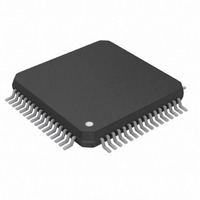
MAX2981GCB/V+T Maxim Integrated Products, MAX2981GCB/V+T Datasheet

MAX2981GCB/V+T
Specifications of MAX2981GCB/V+T
Related parts for MAX2981GCB/V+T
MAX2981GCB/V+T Summary of contents
Page 1
... IPTV Distribution Typical Operating Circuit appears at end of data sheet. HomePlug is a registered trademark of HomePlug Powerline Alliance, Inc. ________________________________________________________________ Maxim Integrated Products For pricing, delivery, and ordering information, please contact Maxim Direct at 1-888-629-4642, or visit Maxim’s website at www.maxim-ic.com. o HomePlug 1.0 Compliant o Fully Integrated AFE and Line Driver ...
Page 2
Integrated Powerline Communication Analog Front-End Transceiver and Line Driver ABSOLUTE MAXIMUM RATINGS AVDD to AGND .....................................................-0.3V to +3.9V DVDD3 to DGND ...................................................-0.3V to +3.9V DVDD to DGND .....................................................-0.3V to +2.8V AGND to DGND.....................................................-0.3V to +0.3V All Other Pins..............................................-0. ...
Page 3
Integrated Powerline Communication Analog Front-End Transceiver and Line Driver ELECTRICAL CHARACTERISTICS (continued +3.3V, DVDD = REGOUT, V AVDD DVDD3 Typical values are +25°C.) (Note 1) A PARAMETER SYMBOL RECEIVER Common-Mode Voltage Input Impedance ...
Page 4
Integrated Powerline Communication Analog Front-End Transceiver and Line Driver PIN NAME 10, 13, 17, 28, 32, 52, AGND Analog Ground 53, 56 12, 15, 16, Analog Power-Supply Voltage. AVDD supply range is 3.0V to ...
Page 5
Integrated Powerline Communication Analog Front-End Transceiver and Line Driver PIN NAME DAC/ADC Input/Output Data Bit 7. Input/output of 10-bit, 50MHz bidirectional digital-to-analog and 36 DAD7 analog-to-digital converter. Data is in binary format. DAC/ADC Input/Output Data Bit 6. Input/output of 10-bit, ...
Page 6
Integrated Powerline Communication Analog Front-End Transceiver and Line Driver PLIP VGA PLIN PLOP LD PLON Detailed Description The MAX2981 powerline communication AFE and line- driver state-of-the-art CMOS device that delivers high performance at low cost. This highly ...
Page 7
Integrated Powerline Communication Analog Front-End Transceiver and Line Driver Transmit Enable (ENTX) The ENTX line enables the transmitter of the MAX2981 AFE circuit. With ENTX and ENREAD driven high, data sent to the DAC through DAD[9:0] is conditioned and delivered ...
Page 8
Integrated Powerline Communication Analog Front-End Transceiver and Line Driver SWR SDAT D15 A0 SCLK Figure 2. Writing Mode Register Timing Diagram Table 1. Register Addresses REGISTER (R/ (R/ (R/W) 0 ...
Page 9
Integrated Powerline Communication Analog Front-End Transceiver and Line Driver Table 3. Register R2 Map REGISTER BIT NO. DEFAULT R2B0 Low Reserved. R2B1 Low Reserved. R2B2 Low Reserved. R2B3 High Reserved. R2B4 Low Reserved. R2B5 Low Reserved. R2B6 Low Reserved. R2B7 ...
Page 10
Integrated Powerline Communication Analog Front-End Transceiver and Line Driver Table 5. Register R4 Map REGISTER BIT NO. DEFAULT R4B0 Low Reserved. R4B1 High Reserved. R4B2 High Reserved. R4B3 High Reserved. R4B4 Low Reserved. R4B5 Low Reserved. R4B[10:6] 01011 Reserved. R4B11 ...
Page 11
Integrated Powerline Communication Analog Front-End Transceiver and Line Driver Applications Information Interfacing to Digital PHY Circuit The MAX2981 interfaces to the MAX2982/MAX2986 digital baseband IC using a bidirectional bus to pass the digital data to and from the DAC and ...
Page 12
... Maxim cannot assume responsibility for use of any circuitry other than circuitry entirely embodied in a Maxim product. No circuit patent licenses are implied. Maxim reserves the right to change the circuitry and specifications without notice at any time. 12 ____________________Maxim Integrated Products, 120 San Gabriel Drive, Sunnyvale, CA 94086 408-737-7600 © 2009 Maxim Integrated Products ...


