DS2180AQN+ Maxim Integrated Products, DS2180AQN+ Datasheet - Page 21
DS2180AQN+
Manufacturer Part Number
DS2180AQN+
Description
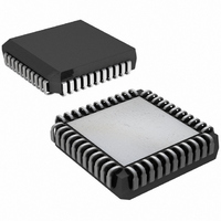
IC TRANSCEIVER T1 IND 44-PLCC
Manufacturer
Maxim Integrated Products
Datasheet
1.DS2180A.pdf
(35 pages)
Specifications of DS2180AQN+
Function
Transceiver
Interface
T1
Number Of Circuits
1
Voltage - Supply
4.5 V ~ 5.5 V
Current - Supply
3mA
Operating Temperature
-40°C ~ 85°C
Mounting Type
Surface Mount
Package / Case
44-LCC, 44-PLCC
Includes
Alarm Generation and Detection, B7 Stuffing Mode, B8ZS Mode, Error Detection and Counter, "Hardware" Mode, Transparent Mode
Lead Free Status / RoHS Status
Lead free / RoHS Compliant
Power (watts)
-


RYEL OUTPUT
The yellow alarm output transitions high when a yellow alarm is detected. A high-low transition indicates
the alarm condition has been cleared. The RYEL bit (RSR.5) is a “latched” version of the RYEL output.
In 193E framing, the yellow alarm pattern detected is 16 pattern sets of 00 (Hex) and FF (Hex) received
at RLINK. In 193S, framing the yellow alarm format is de-pendent on CCR.3; if CCR.3=0, the RYEL
output transitions high if bit 2 of 256 or more consecutive channels is 0; if CCR.3=1, yellow alarm is
declared when the S-bit received in frame 12 is 1.
RBV OUTPUT
The bipolar violation output transitions high when an accused bit emerges at RSER. RBV will go low at
the next bit time if no additional violations are detected.
RFER OUTPUT
The receive frame error output transitions high at the F-bit time and is held high for two bit periods when
a frame bit error occurs. In 193S framing, F
framing. Additionally, in 193E framing, RFER reports a CRC error by a low-high-low transition (one bit
period wide) one half RCLK period before a low-high transition on RMSYNC.
RESET
A high-low transition on
high. This reset has no effect on transmit frame multiframe or channel counters.
system power-up to insure proper initialization of transceiver counters and registers. Following reset, the
host processor should restore all control modes by writing appropriate registers with control data.
ALARM OUTPUT TIMING Figure 21
NOTES:
1. RFER transitions high during F-bit time if received framing pattern bit is in error. (Frame 12 F-bits in
2. RBV indicates received bipolar violation and transitions high when an accused bit emerges from
3. RCL transitions high (during 32nd bit time) when 32 consecutive bits received are 0; RCL transitions
193S are ignored if CCR.3=1). Also, in 193E, RFER transitions 1/2 bit time before the rising edge of
RMSYNC to indicate a CRC error for the previous multiframe.
RSER. If B8ZS is enabled, RBV will not report the zero replacement code.
low when the next 1 is received.
RST
clears all registers and forces immediate receive resync when
T
and F
21 of 35
S
patterns are tested. The FPS pattern is tested in 193E
RST
must be held low on
RST
DS2180A
returns
Related parts for DS2180AQN+
Image
Part Number
Description
Manufacturer
Datasheet
Request
R

Part Number:
Description:
IC TRANSCEIVER T1 40-DIP
Manufacturer:
Maxim Integrated Products
Datasheet:
Part Number:
Description:
IC TRANSCEIVER T1 40-DIP
Manufacturer:
Maxim Integrated Products
Datasheet:


Part Number:
Description:
power light source Luxeon Line
Manufacturer:
LUMILEDS [Lumileds Lighting Company]
Datasheet:

Part Number:
Description:
MAX7528KCWPMaxim Integrated Products [CMOS Dual 8-Bit Buffered Multiplying DACs]
Manufacturer:
Maxim Integrated Products
Datasheet:
Part Number:
Description:
Single +5V, fully integrated, 1.25Gbps laser diode driver.
Manufacturer:
Maxim Integrated Products
Datasheet:
Part Number:
Description:
Single +5V, fully integrated, 155Mbps laser diode driver.
Manufacturer:
Maxim Integrated Products
Datasheet:
Part Number:
Description:
VRD11/VRD10, K8 Rev F 2/3/4-Phase PWM Controllers with Integrated Dual MOSFET Drivers
Manufacturer:
Maxim Integrated Products
Datasheet:
Part Number:
Description:
Highly Integrated Level 2 SMBus Battery Chargers
Manufacturer:
Maxim Integrated Products
Datasheet:
Part Number:
Description:
Current Monitor and Accumulator with Integrated Sense Resistor; ; Temperature Range: -40°C to +85°C
Manufacturer:
Maxim Integrated Products
Part Number:
Description:
TSSOP 14/A�/RS-485 Transceivers with Integrated 100O/120O Termination Resis
Manufacturer:
Maxim Integrated Products
Part Number:
Description:
TSSOP 14/A�/RS-485 Transceivers with Integrated 100O/120O Termination Resis
Manufacturer:
Maxim Integrated Products
Part Number:
Description:
QFN 16/A�/AC-DC and DC-DC Peak-Current-Mode Converters with Integrated Step
Manufacturer:
Maxim Integrated Products
Part Number:
Description:
TDFN/A/65V, 1A, 600KHZ, SYNCHRONOUS STEP-DOWN REGULATOR WITH INTEGRATED SWI
Manufacturer:
Maxim Integrated Products
Part Number:
Description:
Integrated Temperature Controller f
Manufacturer:
Maxim Integrated Products