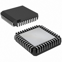
DS2180AQ+ Maxim Integrated Products, DS2180AQ+ Datasheet - Page 18

DS2180AQ+
Manufacturer Part Number
DS2180AQ+
Description
IC TRANSCEIVER T1 44-PLCC
Manufacturer
Maxim Integrated Products
Datasheet
1.DS2180A.pdf
(35 pages)
Specifications of DS2180AQ+
Function
Transceiver
Interface
T1
Number Of Circuits
1
Voltage - Supply
4.5 V ~ 5.5 V
Current - Supply
3mA
Operating Temperature
0°C ~ 70°C
Mounting Type
Surface Mount
Package / Case
44-LCC, 44-PLCC
Includes
Alarm Generation and Detection, B7 Stuffing Mode, B8ZS Mode, Error Detection and Counter, "Hardware" Mode, Transparent Mode
Lead Free Status / RoHS Status
Lead free / RoHS Compliant
Power (watts)
-
RSR: RECEIVE STATUS REGISTER Figure 17
(MSB)
RECEIVE ALARM REPORTING
Incoming serial data is monitored by the transceiver for alarm occurrences. Alarm conditions are reported
in two ways: via transitions on the alarm output pins and registered interrupt, in which the host controller
reads the RSR in response to an alarm-driven interrupt. Interrupts may be direct, in which the transceiver
demands service for a real-time alarm, or count-overflow triggered, in which an onboard alarm event
counter exceeds a user-programmed threshold. The user may mask individual alarm conditions by
clearing the appropriate bits in the receive interrupt mask register (RIMR).
ALARM SERVICING
The host controller must service the transceiver in order to clear an interrupt condition. Clearing
appropriate bits in the RIMR will unconditionally clear an interrupt. Direct interrupt (those driven from
real-time alarms) will be cleared when the RSR is directly read unless the alarm condition still exists.
Count-overflow interrupts (BVCS, ECS) are not cleared by a direct read of the RSR. They will be cleared
only when the user presets the appropriate count register to a value other than all 1’s. A burst read of the
RSR will not clear an interrupt condition.
SYMBOL
BVCS
B8ZSD
BVCS
RYEL
RLOS
FERR
RCL
RBL
ECS
ECS
POSITION
RSR.7
RSR.6
RSR.5
RSR.4
RSR.3
RSR.2
RSR.1
RSR.0
RYEL
NAME AND DESCRIPTION
Bipolar Violation Count Saturation. Set when the 8-bit counter
at BVCR saturates.
Error Count Saturation. Set when either of the 4-bit counters at
ECR saturates.
Receive Yellow Alarm. Set when yellow alarm detected.
(Detected yellow alarm format determined by CCR.4 and CCR.3.)
Receive Carrier Loss. Set when 32 consecutive 0’s appear at
RPOS and RNEG.
Frame Bit Error. Set when F
occurs.
Bipolar Eight Zero Substitution Detect. Set when B8ZS code
word detected.
Receive Blue Alarm. Set when two consecutive frames have less
than three 0’s (total) in the data stream (F-bit positions not tested).
Receive Loss of Sync. Set when resync is in process; if RCR.1=0,
RLOS transitions high on an OOF event or carrier loss indicating
auto resync.
RCL
18 of 35
FERR
B8ZSD
T
(193S) or FPS (193E) bit error
RBL
(LSB)
RLOS
DS2180A


