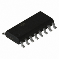
SY55854UYI TR Micrel Inc, SY55854UYI TR Datasheet - Page 2

SY55854UYI TR
Manufacturer Part Number
SY55854UYI TR
Description
IC CROSSPOINT SWITCH 2X2 16-QSOP
Manufacturer
Micrel Inc
Series
SY55r
Specifications of SY55854UYI TR
Function
Crosspoint Switch
Circuit
1 x 2:2
Voltage Supply Source
Single Supply
Voltage - Supply, Single/dual (±)
2.3 V ~ 5.5 V
Current - Supply
60mA
Operating Temperature
-40°C ~ 85°C
Mounting Type
Surface Mount
Package / Case
16-LSSOP (0.154", 3.91mm Width)
Array Configuration
2x2
Number Of Arrays
1
Differential Data Transmission
Yes
Power Supply Requirement
Single
Pin Count
16
Mounting
Surface Mount
Operating Temperature (max)
85C
Operating Temperature (min)
-40C
Operating Temperature Classification
Industrial
On-chip Buffers
No
On-chip Decoder
No
On-chip Latch Circuit
No
On-chip Mux/demux
No
Programmable
No
Dual Supply Voltage (typ)
Not RequiredV
Dual Supply Voltage (max)
Not RequiredV
Dual Supply Voltage (min)
Not RequiredV
Output Level
CML
Lead Free Status / RoHS Status
Contains lead / RoHS non-compliant
Other names
SY55854UYITR
SY55854UYITR
SY55854UYITR
Micrel
Measuring an Eye with SY55854U
using the SY55854U evaluation board.
diagram using the SY55854U evaluation board.
set to about 3.3V. Current consumption will be under 100mA.
Connect the positive power supply to the bottom pin of the
power supply header, marked “V
symbol. Connect the negative power supply to the top pin
of the power supply header.
EVALUATION PROCEDURE
This section describes how to obtain an eye diagram
You will need:
An SY55854U evaluation board
A power supply
A digital signal source capable of generating pseudo-
random patterns at up to 2.5Gbps
An oscilloscope capable of showing eye patterns
Two pairs of length-matched SMA cables
Four 50 termination SMA
The following steps allow the user to generate an eye
1. Connect Power Source: The power supply must be
V
2.3V to 3.0V
3.0V to 5.7V
2.3V to 5.7V
2.3V to 3.0V
3.0V to 5.7V
2.3V to 5.7V
CC
Connection
“S0” open and “/S0” has a 50 cap
“S0” open and “/S0” open
“S0” has a 50 cap and “/S0” open
“S1” open and “/S1” has a 50 cap
“S1” open and “/S1” open
“S1” has a 50 cap and “/S1” open
CC
,” and having a ground
Table 1. Select Settings
2
generate a pseudo-random data stream. Any pattern 2
PRBS or better will do. If there is a choice, use 2
PRBS. Set the data rate to 2.5Gbps. Set the output high
level to be +0V, and the output low level to be –400mV.
the differential output of the signal generator to the “D0”
and the “/D0” SMA connectors.
matched SMA cables, connect “Q0,” and “/Q0” SMA
connectors to the oscilloscope. Connect a trigger output
from the digital generator to the trigger input of the
oscilloscope.
“/D1,” “Q1,” and “/Q1” SMA connectors with 50 terminators.
that the “S0, ”and “/S0,” SMA connectors are open. For
further information regarding how to select various inputs,
please refer to Table 1.
diagram.
2. Connect Data Source: Set your data source to
Using one pair of length matched SMA cables, connect
3. Connect Data Output: Using another pair of length
4. Terminate Unused Inputs and Outputs: Cap the “D1,”
5. Configure the SY55854U Evaluation Board: Ensure
6. View the Eye: Adjust the oscilloscope to show the eye
Function
“Q0” sources “D0”
“Q0” sources “D0”
“Q0” sources “D1”
“Q1” sources “D0”
“Q1” sources “D0”
“Q1” sources “D1”
EVALUATION BOARD
SY55854U
23
7
–1
–1


