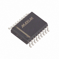
MAX349EWN+ Maxim Integrated Products, MAX349EWN+ Datasheet - Page 16

MAX349EWN+
Manufacturer Part Number
MAX349EWN+
Description
IC MULTIPLEXER 8X1 18SOIC
Manufacturer
Maxim Integrated Products
Type
Analog Multiplexerr
Datasheet
1.MAX350CPN.pdf
(20 pages)
Specifications of MAX349EWN+
Function
Multiplexer
Circuit
1 x 8:1
On-state Resistance
100 Ohm
Voltage Supply Source
Single, Dual Supply
Voltage - Supply, Single/dual (±)
2.7 V ~ 16 V, ±2.7 V ~ 8 V
Current - Supply
1µA
Operating Temperature
-40°C ~ 85°C
Mounting Type
Surface Mount
Package / Case
18-SOIC (0.300", 7.50mm Width)
Number Of Channels
1 Channel
On Resistance (max)
500 Ohms at 3 V
On Time (max)
600 ns at 3.6 V
Off Time (max)
300 ns at 3.6 V
Supply Voltage (max)
16 V
Supply Voltage (min)
2.7 V
Maximum Power Dissipation
762 mW
Maximum Operating Temperature
+ 85 C
Minimum Operating Temperature
- 40 C
Mounting Style
SMD/SMT
Switch Current (typ)
0.007 mA at 5.5 V, - 0.0001 mA at - 5.5 V
Lead Free Status / RoHS Status
Lead free / RoHS Compliant
Serially Controlled, Low-Voltage,
8-Channel/Dual 4-Channel Multiplexers
The MAX350 can be programmed normally, with only
one differential channel selected for every eight clock
pulses, or it can be programmed in a fast mode, where
channel changing occurs on each clock pulse.
In fast mode, select the channels by sending two high
pulses, spaced four clock pulses apart (corresponding
to the two selected channels) at DIN, and a corre-
sponding CS low pulse for each of the first eight clock
pulses. As SCLK clocks this through the register, each
switch sequences one differential channel at a time,
starting with channel 0. Repeat this process for subse-
Figure 3. Connections for MICROWIRE
Figure 5. Daisy-Chained Connection
16
Dual, Differential 4-Channel Multiplexer
______________________________________________________________________________________
THE DOUT-SI CONNECTION IS NOT REQUIRED FOR WRITING TO THE
MAX349/MAX350, BUT MAY BE USED FOR DATA-ECHO PURPOSES.
SCLK
DIN
CS
MAX349
MAX350
DOUT
SCLK
DIN
CS
SCLK
DIN
CS
MAX349
MAX350
SK
SO
SI
I/O
DOUT
MICROWIRE
PORT
SCLK
DIN
CS
MAX349
MAX350
DOUT
quent channel sequencing after the first eight bits have
been sent. For even faster channel sequencing, send
only one DIN high pulse and one CS low pulse for
every four clock pulses.
RESET is the internal reset pin. It is usually connected
to a logic signal or V+. Drive RESET low to open all
switches and set the contents of the internal shift regis-
ter to zero simultaneously. When RESET is high, the
part functions normally and DOUT is sourced from V+.
RESET must not be driven beyond V+ or GND.
Figure 4. Connections for SPI and QSPI
THE DOUT-MISO CONNECTION IS NOT REQUIRED FOR WRITING TO THE
MAX349/MAX350, BUT MAY BE USED FOR DATA-ECHO PURPOSES.
MAX349
MAX350
SCLK
DIN
CS
DOUT
MAX349
MAX350
SCLK
DIN
CS
DOUT
CPOL = 0, CPHA = 0
MISO
MOSI
SCK
I/O
Reset Function
PORT
TO OTHER
SERIAL DEVICES
SPI


