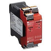
HR2S-332N-T075 IDEC, HR2S-332N-T075 Datasheet - Page 8

HR2S-332N-T075
Manufacturer Part Number
HR2S-332N-T075
Description
47T1445
Manufacturer
IDEC
Datasheet
1.HR2S-301N.pdf
(12 pages)
HR2S-332N-T075/T15/T30 Safety Relay Modules
Terminal Arrangement
HR2S-332N-T075/T15/T30 Wiring Diagram
Safety Category 4 Circuit Example (using an emergency stop switch)
24V DC
ESC:
F1 to 6:
S1:
S2:
S33-Y2: Feedback loop
8 8
10
3
1
9
8
7
2
4
0V
MANU
RESET
S11 S12 S21 S22
S33
HR2S-332N-T075
K1
41
K2
42
POW K1 K2
41
13
Y2
14
42
A1
A2
External Start Condition
Protective fuse for the output of safety relay module
Emergency stop switch with 2NC contacts, safety switch (recommended)
Start Switch
SAFETY
RELAY MODULE
13
14
23
A1
24
AUTO
RESET
23
24
33
A2
33
34
34
K3
K4
57
58
max. 7.5sec
max. 7.5sec
ERR.
57
67
0.5
58
68
0.5
K3 K4
1
1
67
68
77
78
77
78
4
4
45
46
46
45
S11
S21
15
12
13
11
14
5
6
S1
Part Description
Part No.
S22
2
10
11
12
13
14
15
1
2
3
4
5
6
7
8
9
K2
CN1: Power supply input, start/
CN2: Safety input (dual channel)
CN3: Safety output contact
CN4: Safety output contact
CN5: Time-delay safety output
CN6: Time-delay safety output
Switch: Select AUTO or MANU
POW: Power LED
K1: ON-LED for safety output
K2: ON-LED for safety output
ERR: Error (timer) LED
Switches:
Time-delay. The same value
should be set for both switches.
Otherwise, an error occurs.
Characters:
Maximum time-delay duration is
displayed.
0.75: 7.5 sec., 15: 15 sec.,
30: 30 sec.
K3: ON-LED for safety output
K4: ON-LED for safety output
b
Part Names and Functions
1
contact
contact
off-check input
S12
K1
mode
RESET
MANU
S11 S12 S21 S22
S33
HR2S-332N-T075
K1
K2
42
41
POW K1 K2
a
41
13
Y2
14
42
b
SAFETY
RELAY MODULE
13
14
a
23
A1
AUTO
RESET
24
23
24
33
A2
33
34
34
Relay
ON
Sub
S2
S33
AUTO: Short
MANU: Open
K3
K4
Control
Circuit
57
58
Off check
max. 7.5sec
max. 7.5sec
ERR.
57
68
67
0.5
58
Y2
0.5
K3 K4
K3
1
1
ESC
67
68
77
78
K1
K2
77
78
K4
4
4
45
46
45
46
Terminal Arrangement
Note: 5.0A maximum Category 3 or lower
2
1
Terminals Markings
CN1
CN2
CN3
CN4
CN5
CN6
Off-delay Timer Circuit
K3
K4
3.6A maximum Category 4
(1) Use a 3.6A maximum fuse for output
K1
K2
line protection.
A1
A2
S33
Y2
S11
S12
S21
S22
41–42
13–14
23–24
33–34
45–46
57–58
67–68
77–78
13
14
F1
(1)
ERR
23
24
F2
K1
(1)
K2
Stop Category 0
Power supply
+24V DC input
Power supply 0V input
Start/off-check input
Safety
input 1
Safety
input 2
Monitor contact for
safety output (NC)
Safety output contact
(NO)
Time-delay safety
output contact (NC)
Time-delay safety
output contact (NO)
13
14 24
33
34
(1)
23 33
I/O Signals
F3
(1)
34 42
Common
Function
Common
Function
41
K3
Stop Category 1
K4
57
58
K1
K2
57
58
(1)
67
68
F4
(1)
Use a dry contact.
Use a dry contact.
Rated load
250V AC /
30V DC 1A
(Resistive load)
Rated load
250V AC /
30V DC (Note)
(Resistive load)
Rated load
250V AC /
30V DC 1A
(Resistive load)
Rated load
250V AC /
30V DC (Note)
(Resistive load)
77
78
45
46
Remarks
67
68
F5
(1)
(110127)
to PLC
77
78
F6
(1)


