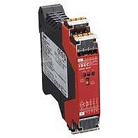
HR2S-301P IDEC, HR2S-301P Datasheet - Page 11

HR2S-301P
Manufacturer Part Number
HR2S-301P
Description
47T1444
Manufacturer
IDEC
Datasheet
1.HR2S-301N.pdf
(12 pages)
Connecting Control Devices
Emergency stop switches
Use emergency stop switches with direct opening action
compliant with EN /IEC 60947-5-1 or EN /IEC 60947-5-5.
Interlock switches
Use interlock switches with direct opening action
mechanism compliant with EN /IEC 60947-5-1.
Safety light curtains and beam sensor switches
Use reliable devices compliant with the required category.
Limitation on safety light curtains:
Short-circuit diagnosis function between OSSDs for safety
light curtains is not provided with this module.
Therefore, category 4 is satisfied by connecting TYPE 4
safety light curtains defined in EN / IEC 61496-1. (TYPE 4
safety light curtain: short-circuit diagnosis function between
OSSDs installed)
OSSD: ESPE connected to the control system of machines
that turns off when the detection device operates during
normal machine operation.
Electromagnetic switches
Use reliable electromagnetic switches with force guided
contact.
If a NC contact of electromagnetic switches, without it being
a force guided contact, is connected to the start/off-check
input, failure of the electromagnetic switch contacts cannot
be detected.
Protection of contact output
For an inductive load, it is recommended to provide a surge
absorber to the output contacts to prevent the contacts from
welding.
When an overvoltage larger than the value rated for output
contact is expected, protect the output contact with a fuse.
Other control devices
•
•
Installation
Mount the module to a panel using DIN rail (35 mm wide).
This module can be mounted in any direction. Install the
module in a control panel with a protection degree of IP54
or better.
When mounting on DIN rails, use an end clip (IDEC BNL6
end clip, optional) to prevent the module from falling off.
(110127)
When connecting other control devices make sure that the
device complies with the required category.
Be sure to turn the power off before switching between
AUTO/MANU.
Below are warnings for the start/off-check input.
AUTO mode:
Do not use a start switch. Otherwise, the contacts of the
start switch may weld and cause unexpected operation
which may lead to hazards.
MANU mode:
When using a start switch, be sure to use NO (normally
open) momentary switches.
For the start/off-check input, use devices with back check
functions (mirror contact). Otherwise, damage may occur
due to failures arising from the start switch and other
causes.
After the AUTO/MANU mode is set, affix a protective tape
to the switch to prevent the setting from being changed.
Instructions
Wiring
Wire size
Stranded wire: 0.2 to 1.5 mm
Solid wire:
Connect after terminating the stranded wire with a ferrule
(sleeve type).
Use wiring compliant with applicable standards.
Close the terminal cover after the wiring is complete. If the
terminal cover does not close, the connector may not be
fully inserted.
Before wiring, make sure that there are no problems with the
wires.
Connect dry voltage contacts to inputs S11 - S12 (S21 -
S22), S33, S34, and Y2.
* Except when connecting safety light curtains.
Precautions when using multiple HR2S modules
A single switch (see SW1 in the diagram below) cannot be
connected to multiple inputs. Use switches with independent
contacts.
(Do not connect one safety device to two HR2S safety
inputs in a parallel connection.)
Note: Same for start/off-check input
Power supply terminal
For an external power supply, be sure to use a switching
power supply compliant with the EMC Directive, IEC 60950,
and NEC CLASS2. Reverse connection of the power supply
may result in damage.
Ferrule (sleeve type): Use crimping metal terminals of 8 to
(Reference)
Weidmuller : H0.5/14, H0.5/16, H0.75/14, H0.75/16, H1/14,
PHOENIX CONTACT: AI0.5-8, AI0.5-10, AI0.75-8, AI0.75-10,
Wiring length
External wiring length of a safety stop input and start/off-
check input is specified as follows:
IDEC does not guarantee normal operation if a wire of a
length other than specified is used.
Safety stop input:
Start/off-check input: Up to 50m in total
SW1
Incorrect
HR2S Safety Relay Modules
S11
S12
S21
S22
S12
S21
S22
S11
H1/16, H1.5/14, H1.5/16
Safety relay module
Safety relay module
0.2 to 1.5 mm
HR2S
HR2S
10 mm in length.
Up to 50m in total
(Wiring resistance: 5Ω maximum)
AI1-8, AI1-10, AI1.5-8, AI1.5-10
2
2
, AWG 24 to 16
, AWG 24 to 16
SW1
SW2
Correct
S11
S12
S21
S22
S11
S12
S21
S22
Safety relay module
Safety relay module
HR2S
HR2S
11
11


