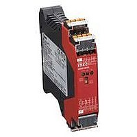
HR2S-301N IDEC, HR2S-301N Datasheet - Page 5

HR2S-301N
Manufacturer Part Number
HR2S-301N
Description
47T1443
Manufacturer
IDEC
Datasheet
1.HR2S-301N.pdf
(12 pages)
HR2S-301P Operation Chart
Using OSSD outputs of a light curtain (EPSE)
Monitor Contact for Safety Output
HR2S-301N Wiring Diagram
Safety Category 4 (3) Circuit Example (using an emergency stop switch)
24V DC
ESC:
F1 to 3:
S1:
S2:
S33-S34: Feedback loop
(110127)
AUTO mode
0V
13-14, 23-24, 33-34 ( NO )
(External Start Condition)
Safety Output Contact
External start condition
Protective fuse for the output of safety relay module
Emergency stop switch with 2NC contacts, safety switch (recommended)
Start Switch
A2
A1
OSSD2 (ESPE )
OSSD1(ESPE)
Start Switch
41-42 ( NC )
S33-S34
ESC
S12
S22
Power ON
S11
Start Switch
Operated
S21
S1
S22
2
HR2S-301P/HR2S-301N Safety Relay Modules
K2
Detecting
Object
b
1
Removing
S12
Object
K1
a
a
b
S2
Relay
ON
Sub
MANU mode
Monitor Contact for Safety Output
S33
MANU: Open
AUTO: Short
Control
Circuit
Off check
S34
13-14, 23-24, 33-34 ( NO )
(External Start Condition)
ESC
K1
K2
Safety Output Contact
K1
K2
Stop Category 0
OSSD1 (ESPE)
OSSD2 ( ESPE )
13
14
Start Switch
41-42 ( NC )
(1)
S33-S34
23 33
24
Safety category is achieved by the entire
control system. Take the connected safety
equipment and wiring into consideration.
ESC
34 42
S12
S22
41
Power ON
to PLC
(1) Use a 3.6A maximum fuse for output
Start Switch
K1
K2
Operated
line protection.
13
14
F1
(1)
23
24
F2
Detecting
(1)
Object
33
34
F3
(1)
Removing
Object
5 5


