14-132.025 EAO, 14-132.025 Datasheet - Page 33
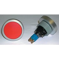
14-132.025
Manufacturer Part Number
14-132.025
Description
30B3860
Manufacturer
EAO
Datasheet
1.704.604.2.pdf
(60 pages)
Specifications of 14-132.025
Contact Configuration
DPST
Switch Operation
(On)
Contact Voltage Ac Nom
250V
Contact Voltage Dc Nom
250V
Contact Current Max
5A
Actuator Style
Round
Switch Terminals
Solder Lug
Rohs Compliant
Yes


Application guidelines
When switching inductive loads such as relays, DC motors, and DC solenoids, it is always important
to absorb surges (e.g. with a diode) to protect the contacts. When these inductive loads are switched
off, a counter emf can severely damage switch contacts and greatly shorten lifetime.
Fig. 1 shows an inductive load with a free-wheeling diode connected in parallel. This free-wheeling
diode provides a path for the inductor current to flow when the current is interrupted by the switch.
Without this free-wheeling diode, the voltage across the coil will be limited only by dielectric break-
down voltages of the circuit or parasitic elements of the coil. This voltage can be kilovolts in amplitude
even when nominal circuit voltages are low (e.g. 12 VDC) see Fig. 2.
The free-wheeling diode should be chosen so that the reverse breakdown voltage is greater than the
voltage driving the inductive load. The DC blocking voltage (VR) of the free-wheeling diode can be
found in the datasheet of a diode. The forward current should be equal or greater than the maximum
current flowing through the load.
To get an efficient protection, the free-wheeling diode must be connected as close as possible
to the inductive load!
0
VDC
Suppressor circuits
+
_
Switching with inductive load
Free-wheeling
Fig. 1
Switch
diode
Inductive
load
over load without free-wheeling diode
Sveral hundred
thousend volts
to several
Counter emf
0
Fig. 2
ON
OFF
e = L
__
dt
di
07.2009
31
14
Related parts for 14-132.025
Image
Part Number
Description
Manufacturer
Datasheet
Request
R

Part Number:
Description:
IC SPI RTC/CALENDAR 14-TSSOP
Manufacturer:
NXP Semiconductors
Datasheet:

Part Number:
Description:
14-BIT BIPOLAR INPUT SINGLE SUPPLY ADC
Manufacturer:
Analog Devices Inc
Datasheet:
Part Number:
Description:
14-BIT BIPOLAR INPUT SINGLE SUPPLY ADC
Manufacturer:
Analog Devices Inc
Datasheet:

Part Number:
Description:
4 CH. SIMULTANEOUS BIPOLAR,14-B ADC I.C.
Manufacturer:
Analog Devices Inc
Datasheet:

Part Number:
Description:
D/A Converter (D-A) IC
Manufacturer:
Analog Devices Inc
Datasheet:

Part Number:
Description:
Header Connector,Cable Mount,PLUG,9 Contacts,SKT,0.1 Pitch,CRIMP Terminal
Manufacturer:
Molex Inc
Datasheet:

Part Number:
Description:
Lamps 2.47V .3A
Manufacturer:
CHICAGO MINIATURE LIGHTING, LLC
Datasheet:

Part Number:
Description:
Manufacturer:
Cypress Semiconductor Corp
Datasheet:

Part Number:
Description:
IC CMOS RTC/CALENDAR 14-TSSOP
Manufacturer:
NXP Semiconductors
Datasheet:

Part Number:
Description:
14 MODII HDR SRST SHRD .100CL
Manufacturer:
TE Connectivity
Datasheet:

Part Number:
Description:
14 MODII HORZ SR CE 100CL
Manufacturer:
Tyco Electronics
Datasheet:
Part Number:
Description:
14 MODI BDMNT RCPT SR .156CL
Manufacturer:
Tyco Electronics
Datasheet:
Part Number:
Description:
IC SPI RTC/CALENDAR 14TSSOP
Manufacturer:
NXP Semiconductors
Datasheet: