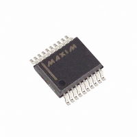
MAX4533CAP Maxim Integrated Products, MAX4533CAP Datasheet - Page 10

MAX4533CAP
Manufacturer Part Number
MAX4533CAP
Description
IC SWITCH QUAD SPDT 20SSOP
Manufacturer
Maxim Integrated Products
Datasheet
1.MAX4533CWP.pdf
(12 pages)
Specifications of MAX4533CAP
Function
Switch
Circuit
4 x SPDT
On-state Resistance
175 Ohm
Voltage Supply Source
Single, Dual Supply
Voltage - Supply, Single/dual (±)
9 V ~ 36 V, ±4.5 V ~ 18 V
Operating Temperature
0°C ~ 70°C
Mounting Type
Surface Mount
Package / Case
20-SSOP
Lead Free Status / RoHS Status
Contains lead / RoHS non-compliant
Available stocks
Company
Part Number
Manufacturer
Quantity
Price
Part Number:
MAX4533CAP
Manufacturer:
MAXIM/美信
Quantity:
20 000
Company:
Part Number:
MAX4533CAP+
Manufacturer:
Maxim
Quantity:
2 000
Part Number:
MAX4533CAP+
Manufacturer:
MAXIM/美信
Quantity:
20 000
The MAX4533 is not a lightning arrester or surge pro-
tector. Exceeding the fault-protection voltage limits on
NO_ or NC_, even for very short periods, can cause the
device to fail.
There is no connection between the analog signal
paths and GND. The analog signal paths consist of an
N-channel and P-channel MOSFET with their sources
and drains paralleled and their gates driven out of
phase to V+ and V- by the logic-level translators.
V+ and GND power the internal logic and logic-level
translators and set the input logic thresholds. The logic-
level translators convert the logic levels to switched V+
and V- signals to drive the gates of the switches. This
Quad, Rail-to-Rail, Fault-Protected,
SPDT Analog Switch
Table 1. Switch States in Normal and Fault Conditions
Figure 2. Switching-Time Test Circuit
10
______________________________________________________________________________________
SUPPLIES
POWER
(V+, V-)
V
On
On
On
On
On
On
Off
COM
V
IN
+10V
-10V
3V
0V
0V
Applications Information
t
OFF
Between V+ and (+40V - V+)
Between V+ and (+40V - V+)
Between V- and (-40V - V-)
Between V- and (-40V - V-)
50%
Between Rails
Between Rails
Between Rails
t
t
ON
50%
t
t
OPEN
R
F
50%
RANGE
< 20ns
< 20ns
INPUT
t
OFF
Failure Modes
50%
t
ON
t
OPEN
50%
Ground
50%
MAX4533
NC_
On
Off
On
Off
On
Off
Off
drive signal is the only connection between the power
supplies and the analog signals. GND, IN_, and COM_
have ESD protection diodes to V+ and V-.
When the logic signals are driven rail-to-rail from 0 to
+12V or -15V to +15V, the supply current reduces to
approximately half of the supply current when the logic
input levels are at 0 to 5V.
The MAX4533 operates with bipolar supplies between
±4.5V and ±18V. The V+ and V- supplies need not be
symmetrical, but their difference can not exceed the
absolute maximum rating of +44V. The MAX4533 oper-
ates from a single supply between +9V and +36V when
V- is connected to GND.
LOGIC
INPUT
Test Circuits/Timing Diagrams
+10V
-10V
IN_
(REPEAT TEST FOR IN2, IN3, AND IN4.)
+15V
V+
NO_
Off
On
Off
On
Off
On
Off
NO_
NC_
Supply Current Reduction
GND
COM_
-15V
V-
SWITCH OUTPUT
Power Supplies
terminal voltage.
Follows the load
OUTPUT
NO_
NC_
2kΩ
V+
V+
V-
V-


