A25L016-F AMIC, A25L016-F Datasheet - Page 21
A25L016-F
Manufacturer Part Number
A25L016-F
Description
58T1299
Manufacturer
AMIC
Datasheet
1.A25L016-F.pdf
(42 pages)
Specifications of A25L016-F
Memory Type
Flash
Memory Size
16Mbit
Memory Configuration
16M X 1
Interface Type
Serial, SPI
Clock Frequency
100MHz
Supply Voltage Range
2.7V To 3.6V
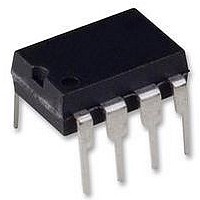
Memory Case Style
DIP
No. Of Pins
8
Rohs Compliant
Yes


Sector Erase (SE)
The Sector Erase (SE) instruction sets to 1 (FFh) all bits
inside the chosen sector. Before it can be accepted, a Write
Enable (WREN) instruction must previously have been ex-
ecuted. After the Write Enable (WREN) instruction has been
decoded, the device sets the Write Enable Latch (WEL).
The Sector Erase (SE) instruction is entered by driving Chip
Select (
Data Input (DIO). Chip Select (
entire duration of the sequence.
The instruction sequence is shown in Figure 13. Chip Select
(
code has been latched in, otherwise the Sector Erase
Figure 13. Sector Erase (SE) Instruction Sequence
(August, 2011, Version 1.6)
S
) must be driven High after the eighth bit of the instruction
S
) Low, followed by the instruction code on Serial
DIO
C
S
Note:. Address bits A23 to A21 are Don’t Care, for A25L016
S
0 1
) must be driven Low for the
2 3 4
Instruction
5 6
7
MSB
23
23
8
20
22 21
instruction is not executed. As soon as Chip Select (
driven High, the self-timed Sector Erase cycle (whose
duration is t
progress, the Status Register may be read to check the value
of the Write In Progress (WIP) bit. The Write In Progress
(WIP) bit is 1 during the self-timed Sector Erase cycle, and is
0 when it is completed. At some unspecified time before the
cycle is completed, the Write Enable Latch (WEL) bit is reset.
A Sector Erase (SE) instruction applied to a page which is
protected by the Block Protect (TB, BP2, BP1, BP0) bits (see
table 1 and table 2) is not executed.
9
24-Bit Address
10
3 2 1
28 29 30 31
SE
) is initiated. While the Sector Erase cycle is in
.
0 0
AMIC Technology Corp.
A25L016 Series
S
) is
Related parts for A25L016-F
Image
Part Number
Description
Manufacturer
Datasheet
Request
R

Part Number:
Description:
2m X 16 Bit X 4 Banks Synchronous Dram - Amic Technology
Manufacturer:
AMIC Technology Corporation
Datasheet:

Part Number:
Description:
58T1324
Manufacturer:
AMIC
Datasheet:
Part Number:
Description:
Manufacturer:
AMIC Technology Corporation
Datasheet:
Part Number:
Description:
Manufacturer:
AMIC Technology Corporation
Datasheet:
Part Number:
Description:
Manufacturer:
AMIC Technology Corporation
Datasheet:
Part Number:
Description:
Manufacturer:
AMIC Technology Corporation
Datasheet:
Part Number:
Description:
Manufacturer:
AMIC Technology Corporation
Datasheet:
Part Number:
Description:
Manufacturer:
AMIC Technology Corporation
Datasheet:
Part Number:
Description:
Manufacturer:
AMIC Technology Corporation
Datasheet:
Part Number:
Description:
Manufacturer:
AMIC Technology Corporation
Datasheet:
Part Number:
Description:
Manufacturer:
AMIC Technology Corporation
Datasheet:
Part Number:
Description:
Manufacturer:
AMIC Technology Corporation
Datasheet:
Part Number:
Description:
Manufacturer:
AMIC Technology Corporation
Datasheet:
Part Number:
Description:
Manufacturer:
AMIC Technology Corporation
Datasheet:
Part Number:
Description:
Manufacturer:
AMIC Technology Corporation
Datasheet: