9767-12-4-417 Amphenol Industrial Operations, 9767-12-4-417 Datasheet - Page 8
9767-12-4-417
Manufacturer Part Number
9767-12-4-417
Description
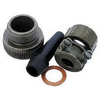
01H9424
Manufacturer
Amphenol Industrial Operations
Datasheet
1.AN3066-4.pdf
(44 pages)
Specifications of 9767-12-4-417
Connector Shell Size
10SL / 12 / 12S
Cable Diameter Max
5.55mm
Peak Reflow Compatible (260 C)
No
Cable Gland Material
Zinc Alloy
Rohs Compliant
No
Approval Categories
MIL-C-5015
Cable Bundle Diameter Max
0.219"
Cable Diameter
5.55mm
For Use With
MS/97 Type Connector


97 series solder type
insert availability
Insert Number
8S-1
10SL-3
10SL-4
12SL-844
12S-3
12-5
12S-6
14S-1†
14S-2
14S-4
14S-5
14S-6
14S-7
14S-9†
16S-1
16S-4
16S-5
16S-6
16-7
16S-8
16-9
16-10
16-11
16-12
16-13
18-1
18-3†
18-4
18-5
18-8
18-9
18-10†
18-11
18-12†
18-13
18-16
18-19†
18-20
18-22†
18-29
18-420*
20-3†
F
F
F
F
F
F
F
F
F
F
†
†
*
†
†
F
*
Contacts
Total
10
10
1
3
2
4
2
1
2
3
4
1
5
6
3
2
7
2
3
3
3
5
4
3
2
1
2
2
4
3
8
7
4
5
6
4
1
5
3
5
1
3
1/16
1/16
1/16
1/16
1/16
1/8
1/16
1/16
1/8
1/16
1/16
1/16
1/8
1/16
1/16
1/16
1/16
1/16
1/16
1/16
1/16
1/16
1/16
1/8
1/8
1/8
1/16
1/16
1/16
1.16
1/16
5/16
1/16
1/16
1/8
1/16
1/8
Inches
Mechanical
Spacing
1.57
1.57
1.57
1.57
1.57
3.18
1.57
1.57
3.18
1.57
1.57
1.57
3.18
1.57
1.57
1.57
1.57
1.57
1.57
1.57
1.57
1.57
1.57
3.18
3.18
3.18
1.57
1.57
1.57
1.57
1.57
7.92
1.57
1.57
3.18
1.57
3.18
mm
Service
Rating
INST.
INST.
INST.
INST.
INST.
INST
D
D
D
D
D
D
C
D
D
A
A
A
A
A
A
A
A
A
A
A
A
A
A
A
A
A
A
A
A
A
A
A
A
A
A
0
1
4
Contact Size
1
1
8
Thermo-
Hi-Volt-
couple
age**
12
1
2
3
2
2
2
2
1
2
4
5
3
1
1
3
Thermo-
couple
10
16
1
3
2
4
2
2
3
4
1
5
6
3
2
7
2
3
3
2
5
2
4
6
4
1
7
5
6
5
3
5
6
Not all insert arrangements are currently available for environmental individual
wire seal. Consult Amphenol, Sidney, NY for availability.
† Inactive for new military design, but available for replacement or for non-military
* “MS” number not assigned. Use “97” prefix in place of “MS” in completing cata-
** Hi-Voltage = 17KVAC/24KVDC
F
Insert Number
20-4
20-6†
20-7
20-8
20-11†
20-14
20-15
20-16
20-17
20-18
20-19†
20-21
20-23
20-24
20-27
20-29
20-33
22-1†
22-2
22-4†
22-5
22-8†
22-9
22-10
22-11
22-12
22-13†
22-14
22-15
22-16†
22-18
22-19
22-20†
22-22
22-23
purposes.
log number. See how to order, page 21.
Molded-in pin (MIP) insert requires (910) deviation. See how to order, pg. 21.
Contacts
Total
13
14
17
11
19
14
4
3
8
6
5
7
9
6
9
3
9
2
4
2
3
4
6
2
3
4
2
5
5
6
9
8
9
4
8
1/8
1/8
1/8
1/16
1/16
1/16
1/16
1/16
1/16
1/16
1/16
1/16
1/16
1/16
1/16
1/16
1/8
1/8
1/16
1/8
3/16
3/16
3/16
1/4
1/8
1/8
1/16
1/16
3/16
1/16
1/16
1/8
1/16
1/16
1/16
1/16
1/8
1/16
Inches
Mechanical
Spacing
3.18
3.18
3.18
1.57
1.57
1.57
1.57
1.57
1.57
1.57
1.57
1.57
1.57
1.57
1.57
1.57
3.18
3.18
1.57
3.18
4.75
4.75
4.75
6.35
3.18
3.18
1.57
1.57
4.75
1.57
1.57
3.18
1.57
1.57
1.57
1.57
3.18
1.57
mm
Service
Rating
INST.
INST.
D
D
D
A
A
A
A
A
A
A
A
A
A
A
A
A
D
D
A
D
E
E
E
B
D
D
A
A
E
A
A
D
A
A
A
A
D
A
0
4
Contact Size
8
2
2
3
2
2
2
3
2
2
4
12
4
3
7
2
5
3
1
2
2
2
3
4
5
3
1
7
13
14
17
11
19
14
16
3
4
4
4
7
1
6
8
2
4
4
2
3
1
1
6
5
3
9
Related parts for 9767-12-4-417
Image
Part Number
Description
Manufacturer
Datasheet
Request
R

Part Number:
Description:
CABLE CLAMP SIZE 10SL/12S/12, ZINC ALLOY
Manufacturer:
Amphenol Industrial Operations
Datasheet:
Part Number:
Description:
CABLE CLAMP, SIZE 24/28, ZINC ALLOY
Manufacturer:
Amphenol Industrial Operations
Datasheet:
Part Number:
Description:
CABLE CLAMP, SIZE 20/22, ZINC ALLOY
Manufacturer:
Amphenol Industrial Operations
Datasheet:

Part Number:
Description:
01H9429
Manufacturer:
Amphenol Industrial Operations
Datasheet:
Part Number:
Description:
CABLE CLAMP SIZE 10SL/12S/14, ZINC ALLOY
Manufacturer:
Amphenol Industrial Operations
Datasheet:

Part Number:
Description:
JAM NUT CONN, RCPT, SIZE 9, 6POS, PANEL
Manufacturer:
Amphenol Industrial Operations
Datasheet:

Part Number:
Description:
PT 41C 41#20 PIN RECP
Manufacturer:
Amphenol Industrial Operations
Part Number:
Description:
PT 41C 41#20 SKT RECP
Manufacturer:
Amphenol Industrial Operations