FLUKE-190-204/AM Fluke Electronics, FLUKE-190-204/AM Datasheet - Page 5
FLUKE-190-204/AM
Manufacturer Part Number
FLUKE-190-204/AM
Description
SCOPEMETER 4CH 200MHZ COLOR AMER
Manufacturer
Fluke Electronics
Series
ScopeMeter® 190r
Type
Handheldr
Datasheets
1.FLUKE-190-062AMS.pdf
(8 pages)
2.FLUKE-190-062AMS.pdf
(10 pages)
3.FLUKE-190-104AMS.pdf
(158 pages)
Specifications of FLUKE-190-204/AM
Bandwidth
200MHz
Channels
4
Display Type
LCD - Color
Features
DMM, USB Interface, Save, Recall, Record, Trend
Probe Type
10:1 Voltage Probe (1 Blue, 1 Green, 1 Red, 1 Gray)
Sampling Rate (per Second)
1.25GS/s
Input Impedance
1M
Rise Time (typ)
1.7nS
Voltage - Input (max)
CAT III 1000V, CAT IV 600V
Voltage - Supply
7.2V Battery, 17.8VDC Adapter
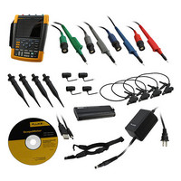
Includes
Alligator Clips, Battery Charger/Adapter, Case, Hook Clips, Probe Set, Software, Test Leads, USB Cable
Lead Free Status / Rohs Status
Lead free / RoHS Compliant
Other names
614-1174


5
What could you
do with four
channels?
Take multiple measurements
simultaneously to track down the
root cause of your most complex
troubleshooting challenges.
Easily diagnose timing-related issues
with multiple signals
• Real-time inspection of multiple related
• Measure a combination of input and output
Find problems in industrial systems
including:
• Circuit voltage/current overloading
• Attenuation/input impedance mismatch
• Signal fluctuation/drift
• Conditioning circuits signal integrity
• Test point verification for critical signals
• Input/output/feedback timing issues
• Induced noise and disturbances
• Random shutdowns/reset
Diagnose VSDs* or power inverters and
converters
• Harmonics, transients and loads in three-
• Troubleshoot dc to ac converters for faulty
• Cable interface—test PWM output for reflec-
• Vpwm measurement to measure the effective
*Variable Speed Drive
signals simultaneously
signals and system safety interlocks and
feedback loops
phase power input
control circuits or output IGBT gate stages
tions and transients
voltage on drive outputs
For industrial electronics, four channels allow you to
perform three-dimensional testing, measuring input,
output and feedback signals simultaneously.
In three-phase systems like variable speed drives, UPS or
back-up generators, use four channels to diagnose power
input, dc to ac converters, or cable interface problems.
Gnd
supply
L1
L2
L3
Mains
Mechanical
Input
output
Analog
Digital
conversion
AC to DC
Power Supply
voltage
and buffer
bus
DC
Motor (load)
Process/Display
Safety control
lter
-Vdc
+Vdc
Feedback
Analog/Digital
DC to AC converter
Transducers
Measurements’
Cable interface
Output
Condition
T3
T2
T1
T1
T2
T3