ZMOT0BSB1A0CG Zilog, ZMOT0BSB1A0CG Datasheet - Page 14
ZMOT0BSB1A0CG
Manufacturer Part Number
ZMOT0BSB1A0CG
Description
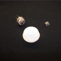
Processors - Application Specialized ZMB N SBDI46-504AA P Nic. NCL-9(26) Lens
Manufacturer
Zilog
Datasheet
1.ZMOT0BSB0A0AG.pdf
(65 pages)
Specifications of ZMOT0BSB1A0CG
Operating Supply Voltage
2.7 V to 3.6 V
Maximum Operating Temperature
+ 105 C
Mounting Style
SMD/SMT
Package / Case
SOIC-8
Core
Z8FS040
Number Of Timers
2
Processor Series
ZMOTION
Program Memory Size
4 KB
Program Memory Type
Flash
Lead Free Status / Rohs Status
Details


PS028511-0112
Signal Mnemonic
General-Purpose I/O Ports A–D
PA[7:0]
PB[5:0]
PC[7:0]
PD[0]
UART Controllers
TXD0
RXD0
CTS0
DE
Timers
T0
T0
T0
Comparator
C
C
IN
OUT
OUT
OUT
IN
P/C
/T1IN
Signal Descriptions
/T1
/T1
IN
N
OUT
OUT
At reset, all port pins are set to the GPIO input state on the 8-pin SOIC package except for
RESET/DE0/T1
which is configured to DBG. On the 20- and 28-pin SSOP packages, RESET/PD0 is con-
figured to RESET.
Table 3 describes the Z8FS040 Series signals.
I/O
I/O
I/O
I/O
O
O
I
I
O
O
O
I
I
O
Table 3. Z8FS040 MCU Signal Descriptions
OUT
Description
Port A. These pins are used for general-purpose I/O.
Port B. These pins are used for general-purpose I/O.
Port C. These pins are used for general-purpose I/O.
IrDA.
Receive Data. This signal is the receive input for the UART and IrDA.
drivers. It is approximately the inverse of the Transmit Empty (TXE) bit in
the UART Status 0 Register. The DE signal can be used to ensure that
the external RS-485 driver is enabled when data is transmitted by the
UART.
Timer Output 0–1. These signals are outputs from the timers.
Timer Complement Output 0–1. These signals are output from the timers
in PWM DUAL OUTPUT Mode.
Timer Input 0–1. These signals are used as the capture, gating and
counter inputs.
Comparator Inputs. These signals are the positive and negative inputs to
the comparator.
Comparator Output.
Port D. This pin is used for general-purpose output only.
Transmit Data. This signal is the transmit output from the UART and
Clear To Send. This signal is the flow control input for the UART.
Driver Enable. This signal allows automatic control of external RS-485
, which is configured to RESET, and PA0/T0
ZMOTION™ Detection and Control Family
Product Specification
IN
/T0
OUT
Signal Descriptions
/X
IN
/DBG,
7
Related parts for ZMOT0BSB1A0CG
Image
Part Number
Description
Manufacturer
Datasheet
Request
R

Part Number:
Description:
Communication Controllers, ZILOG INTELLIGENT PERIPHERAL CONTROLLER (ZIP)
Manufacturer:
Zilog, Inc.
Datasheet:

Part Number:
Description:
KIT DEV FOR Z8 ENCORE 16K TO 64K
Manufacturer:
Zilog
Datasheet:

Part Number:
Description:
KIT DEV Z8 ENCORE XP 28-PIN
Manufacturer:
Zilog
Datasheet:

Part Number:
Description:
DEV KIT FOR Z8 ENCORE 8K/4K
Manufacturer:
Zilog
Datasheet:

Part Number:
Description:
KIT DEV Z8 ENCORE XP 28-PIN
Manufacturer:
Zilog
Datasheet:

Part Number:
Description:
DEV KIT FOR Z8 ENCORE 4K TO 8K
Manufacturer:
Zilog
Datasheet:
Part Number:
Description:
CMOS Z8 microcontroller. ROM 16 Kbytes, RAM 256 bytes, speed 16 MHz, 32 lines I/O, 3.0V to 5.5V
Manufacturer:
Zilog, Inc.
Datasheet:
Part Number:
Description:
Low-cost microcontroller. 512 bytes ROM, 61 bytes RAM, 8 MHz
Manufacturer:
Zilog, Inc.
Datasheet:
Part Number:
Description:
Z8 4K OTP Microcontroller
Manufacturer:
Zilog, Inc.
Datasheet:
Part Number:
Description:
CMOS SUPER8 ROMLESS MCU
Manufacturer:
Zilog, Inc.
Datasheet:
Part Number:
Description:
SL1866 CMOSZ8 OTP Microcontroller
Manufacturer:
Zilog, Inc.
Datasheet:
Part Number:
Description:
SL1866 CMOSZ8 OTP Microcontroller
Manufacturer:
Zilog, Inc.
Datasheet:
Part Number:
Description:
OTP (KB) = 1, RAM = 125, Speed = 12, I/O = 14, 8-bit Timers = 2, Comm Interfaces Other Features = Por, LV Protect, Voltage = 4.5-5.5V
Manufacturer:
Zilog, Inc.
Datasheet:
Part Number:
Description:
Manufacturer:
Zilog, Inc.
Datasheet: