HI3-5051-5 Intersil, HI3-5051-5 Datasheet
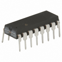
IC SWITCH DUAL SPDT 16DIP

HI3-5051-5

Manufacturer Part Number
HI3-5051-5
Description
IC SWITCH DUAL SPDT 16DIP
Manufacturer
Intersil
Datasheet

Specifications of HI3-5051-5

Function
Switch
Circuit
2 x SPDT
On-state Resistance
45 Ohm
Voltage Supply Source
Dual Supply
Voltage - Supply, Single/dual (±)
±14 V ~ 16 V
Operating Temperature
0°C ~ 75°C
Mounting Type
Through Hole
Package / Case
16-DIP (0.300", 7.62mm)
Lead Free Status / RoHS Status
Contains lead / RoHS non-compliant

Available stocks

Company
Part Number
Manufacturer
Quantity
Price
Part Number:
HI3-5051-5
Manufacturer:
HARRIS
Quantity:
33
Part Number:
HI3-5051-5
Manufacturer:
AMD
Quantity:
6 225
Part Number:
HI3-5051-5
Manufacturer:
HARRIS
Quantity:
1 000
Part Number:
HI3-5051-5
Manufacturer:
HARRIS
Quantity:
20 000
Part Number:
HI3-5051-5Z
Manufacturer:
Intersil
Quantity:
150
CMOS Analog Switches
This family of CMOS analog switches offers low resistance
switching performance for analog voltages up to the supply
rails and for signal currents up to 80mA. “ON” resistance is
low and stays reasonably constant over the full range of
operating signal voltage and current. r
exceptionally constant for input voltages between +5V and
-5V and currents up to 50mA. Switch impedance also
changes very little over temperature, particularly between
0
HI-5051 and 50Ω for HI-5042 through HI-5047.
All devices provide break-before-make switching and are
TTL and CMOS compatible for maximum application
versatility. Performance is further enhanced by Dielectric
Isolation processing which insures latch-free operation with
very low input and output leakage currents (0.8nA at 25
This family of switches also features very low power
operation (1.5mW at 25
There are 7 devices in this switch series which are
differentiated by type of switch action and value of r
Functional Description Table). The HI-504X and HI-505X series
switches can directly replace IH-5040 series devices, and are
functionally compatible with the DG180 and DG190 family
o
C and 75
o
C. r
ON
is nominally 25Ω for HI-5049 and
o
C).
®
1
Data Sheet
ON
remains
HI-5042, HI-5043, HI-5047, HI-5049, HI-5051
ON
(see
1-888-INTERSIL or 1-888-352-6832
o
C).
CAUTION: These devices are sensitive to electrostatic discharge; follow proper IC Handling Procedures.
Features
• Wide Analog Signal Range . . . . . . . . . . . . . . . . . . . ±15V
• Low “ON” Resistance . . . . . . . . . . . . . . . . . . . . . . . . . 25Ω
• High Current Capability . . . . . . . . . . . . . . . . . . . . . . 80mA
• Break-Before-Make Switching
• No Latch-Up
• Input MOS Gates are Protected from Electrostatic
• DTL, TTL, CMOS, PMOS Compatible
• Pb-Free Available (RoHS Compliant)
Applications
• High Frequency Switching
• Sample and Hold
• Digital Filters
• Operational Amplifier Gain Switching
Functional Diagram
Functional Description
HI-5042
HI-5043
HI-5047
HI-5049
HI-5051
- Turn-On Time . . . . . . . . . . . . . . . . . . . . . . . . . . . . 370ns
- Turn-Off Time . . . . . . . . . . . . . . . . . . . . . . . . . . . 280ns
Discharge
PART NUMBER
A
All other trademarks mentioned are the property of their respective owners.
April 6, 2005
|
Intersil (and design) is a registered trademark of Intersil Americas Inc.
Copyright Intersil Americas Inc. 2001, 2005. All Rights Reserved
SPDT
Dual SPDT
4PST
Dual DPST
Dual SPDT
N
TYPE
P
FN3127.6
S
50Ω
50Ω
50Ω
25Ω
25Ω
r
D
ON

Related parts for HI3-5051-5

HI3-5051-5 Summary of contents

Page 1

... All other trademarks mentioned are the property of their respective owners. FN3127 TYPE SPDT 50Ω Dual SPDT 50Ω 4PST 50Ω Dual DPST 25Ω Dual SPDT 25Ω Intersil (and design registered trademark of Intersil Americas Inc. Copyright Intersil Americas Inc. 2001, 2005. All Rights Reserved ...

Page 2

... Ld CERDIP HI1-5049 CERDIP HI1-5051-2 -55 to 125 16 Ld CERDIP HI1-5051 CERDIP HI3-5051 PDIP HI3-5051- PDIP * (See Note) (Pb-free) HI9P5051-9 - SOIC HI9P5051-9Z - SOIC (See Note) (Pb-free) *Pb-free PDIPs can be used for through hole wave solder processing only. They are not intended for use in Reflow solder processing applications ...

Page 3

Switch Functions (SWITCHES SHOWN FOR LOGIC “1” INPUT) SPDT HI-5042 (50Ω 4PST HI-5047 (50Ω ...

Page 4

Schematic Diagrams V L QP3 QP5 QP8 NOTE: Connect for minimizing power consumption when driving from CMOS circuits 200Ω ...

Page 5

Absolute Maximum Ratings Supply Voltage ( 36V V to ...

Page 6

Electrical Specifications Supplies = +15V, -15V; V Unless Otherwise Specified. For Test Conditions, Consult Performance Characteristics, Unused Pins are Grounded (Continued) PARAMETER OFF Input or Output Leakage Current S(OFF) D(OFF) ON Leakage Current, I D(ON) POWER REQUIREMENTS ...

Page 7

Test Circuits and Waveforms 100nA S(OFF) D(OFF) 10nA 1nA I D(ON) 100pA 10pA TEMPERATURE ( FIGURE 2A. LEAKAGE CURRENTS vs TEMPERATURE 1.4 1.3 1.2 1.1 1 ANALOG CURRENT (mA) FIGURE 3A. ...

Page 8

Test Circuits and Waveforms -200 -160 -120 - 10kΩ 100 1K 10K FREQUENCY (Hz) FIGURE 5A. CROSSTALK vs FREQUENCY 200 160 120 10K TOGGLE FREQUENCY (50% DUTY CYCLE) (Hz) ...

Page 9

Test Circuits and Waveforms V A OUTPUT Vertical: 2V/Div. Horizontal: 200ns/Div. FIGURE 7C. WAVEFORMS WITH TTL COMPATIBLE LOGIC INPUT 720 660 600 540 480 420 t ON 360 300 t OFF 240 180 120 ...

Page 10

Dual-In-Line Plastic Packages (PDIP INDEX N/2 AREA -B- -A- D BASE PLANE -C- SEATING PLANE 0.010 (0.25 NOTES: 1. Controlling Dimensions: INCH. In case of conflict between ...

Page 11

Small Outline Plastic Packages (SOIC) N INDEX 0.25(0.010) H AREA E - SEATING PLANE - -C- α µ 0.10(0.004) 0.25(0.010 NOTES: 1. Symbols are defined in ...

Page 12

... Accordingly, the reader is cautioned to verify that data sheets are current before placing orders. Information furnished by Intersil is believed to be accurate and reliable. However, no responsibility is assumed by Intersil or its subsidiaries for its use; nor for any infringements of patents or other rights of third parties which may result from its use ...

Related keywords