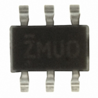
PI5A3157CEX Pericom Semiconductor, PI5A3157CEX Datasheet - Page 5

PI5A3157CEX
Manufacturer Part Number
PI5A3157CEX
Description
IC ANLG SW/MUX/DEMUX SPDT SC70-6
Manufacturer
Pericom Semiconductor
Type
Analog Switchr
Datasheet
1.PI5A3157CEX.pdf
(8 pages)
Specifications of PI5A3157CEX
Function
Switch
Circuit
1 x SPDT
On-state Resistance
13 Ohm
Voltage Supply Source
Single Supply
Voltage - Supply, Single/dual (±)
1.65 V ~ 5.5 V
Current - Supply
1µA
Operating Temperature
-40°C ~ 85°C
Mounting Type
Surface Mount
Package / Case
6-TSSOP, SC-88, SOT-363
Switch Configuration
SPDT
On Resistance (max)
39 Ohms @ 1.65 V
On Time (max)
23 ns @ 1.95 V
Off Time (max)
12.5 ns @ 1.95 V
Supply Voltage (max)
5.5 V
Supply Voltage (min)
1.65 V
Maximum Power Dissipation
180 mW
Maximum Operating Temperature
+ 85 C
Mounting Style
SMD/SMT
Description/function
Audio Switch SPDT
Minimum Operating Temperature
- 40 C
Propagation Delay Time
1.2 ns (Typ)@2.7V/0.8 ns (Typ)@3.6V/0.3 ns (Typ)@5.5V
Multiplexer Configuration
Single SPDT
Number Of Inputs
1
Number Of Outputs
2
Number Of Channels
1
Analog Switch On Resistance
39@1.65VOhm
Package Type
SC-70
Power Supply Requirement
Single
Single Supply Voltage (min)
1.65V
Single Supply Voltage (typ)
3/5V
Single Supply Voltage (max)
5.5V
Dual Supply Voltage (min)
Not RequiredV
Dual Supply Voltage (typ)
Not RequiredV
Dual Supply Voltage (max)
Not RequiredV
Power Dissipation
180mW
Mounting
Surface Mount
Pin Count
6
Operating Temp Range
-40C to 85C
Operating Temperature Classification
Industrial
Lead Free Status / RoHS Status
Lead free / RoHS Compliant
Other names
PI5A3157CEX
Available stocks
Company
Part Number
Manufacturer
Quantity
Price
Part Number:
PI5A3157CEX
Manufacturer:
PERICO
Quantity:
20 000
1 2 3 4 5 6 7 8 9 0 1 2 3 4 5 6 7 8 9 0 1 2 3 4 5 6 7 8 9 0 1 2 1 2 3 4 5 6 7 8 9 0 1 2 3 4 5 6 7 8 9 0 1 2 3 4 5 6 7 8 9 0 1 2 1 2 3 4 5 6 7 8 9 0 1 2 3 4 5 6 7 8 9 0 1 2 3 4 5 6 7 8 9 0 1 2 1 2 3 4 5 6 7 8 9 0 1 2 3 4 5 6 7 8 9 0 1 2 3 4 5 6 7 8 9 0 1 2 1 2 3 4 5 6 7 8 9 0 1 2
1 2 3 4 5 6 7 8 9 0 1 2 3 4 5 6 7 8 9 0 1 2 3 4 5 6 7 8 9 0 1 2 1 2 3 4 5 6 7 8 9 0 1 2 3 4 5 6 7 8 9 0 1 2 3 4 5 6 7 8 9 0 1 2 1 2 3 4 5 6 7 8 9 0 1 2 3 4 5 6 7 8 9 0 1 2 3 4 5 6 7 8 9 0 1 2 1 2 3 4 5 6 7 8 9 0 1 2 3 4 5 6 7 8 9 0 1 2 3 4 5 6 7 8 9 0 1 2 1 2 3 4 5 6 7 8 9 0 1 2
Test Circuits and Timing Diagrams
Logic
V
Input
IN
OUTPUT
t r = 2.5ns
SWITCH
INPUT
10%
B
B
A
0
1
Output
Under
From
Test
t
PLH
50%
90%
50%
A
t
W
Figure 3. Break Before Make Interval Timing
Notes:
90%
50%
R
Input driven by 50W source terminated in 50Ω.
C L includes load and stray capacitance.
Input PRR = 1.0 MHz; t w = 500ns.
L
50%
t
PHL
10%
Figure 1. AC Test Circuit
Figure 2. AC Waveforms
t r = 2.5ns
C L
10pF
C
L
V
GND
V
V
CC
OH
OL
V
OUT
t r = 2.5ns
5
CONTROL
OUTPUT
OUTPUT
INPUT
100Ω
10%
V
Logic
Input
OUT
SOT
t
t
PZH
50%
PZL
90%
INY
50%
50%
TM
90%
Low Voltage SPDT Analog Switch
50%
2:1 Mux/Demux Bus Switch
10%
t
D
t r = 2.5ns
t
PHZ
t
PLZ
V
V
V
V
OL
OL
OH
OH
V
+0.3V
GND
–0.3V
CC
0.9 x V
V
V
TRI
TRI
PS8552D
OUT
PI5A3157
02/24/05


