CASR 6-NP LEM USA Inc, CASR 6-NP Datasheet - Page 13
CASR 6-NP
Manufacturer Part Number
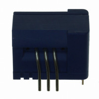
CASR 6-NP
Description
SENSOR CURRENT 6A 5V MOD
Manufacturer
LEM USA Inc
Series
CASRr
Datasheet
1.CASR_25-NP.pdf
(17 pages)
Specifications of CASR 6-NP
Current - Sensing
6A
Accuracy
±0.8%
Sensitivity
104.2mV/A
Current - Supply
-
Sensor Type
Flux Gate
Voltage - Supply
4.75 V ~ 5.25 V
Output
0 ~ 5 VDC
Frequency
300kHz
Response Time
300ns
Polarization
Bidirectional
Operating Temperature
-40°C ~ 85°C
Package / Case
Module
Lead Free Status / Rohs Status
Lead free / RoHS Compliant
Other names
398-1091-5


Electrical offset
The electrical offset voltage V
the ferro-magnetic parts of the transducer are:
●
●
Using the current cycle shown in figure 30, the electrical offset
is:
The temperature variation V
V
considered temperature:
Note: the transducer has to be demagnetized prior to the
application of the current cycle (for example with a
demagnetization tunnel).
Figure 31: Test connection
Filtering and decoupling
Supply voltage V
The fluxgate oscillator draws current pulses of up to 30 mA at
a rate of ca. 900 kHz. Significant 900 kHz voltage ripple on
V
frequencies the power supply rejection ratio is low, and the
ripple may appear on the transducer output V
V
the case of a power supply with high impedance, it is advised
to provide local decoupling (100 nF or more, located close to
the transducer)
Output V
The output V
typically 2 Ohms; it can drive 100 pF directly. Adding series
Rf = 100 Ohms allows much larger capacitive loads. Empirical
evaluation may be necessary to obtain optimum results.
The minimum load resistance on V
100527/4
OE
C
REF
completely demagnetized, which is difficult to realize,
or in a known magnetization state, like in the current cycle
shown in figure 30.
can indicate a power supply with high impedance. At these
is the variation of the electrical offset from 25°C to the
. The transducer has internal decoupling capacitors, but in
10 9 8
1 2 3
OUT
OUT
has a very low output impedance of
V
V
OE
OT
C
Performance parameters definition (continued)
(
=
T
LEM reserves the right to carry out modifications on its transducers, in order to improve them, without prior notice.
V
)
OT
OUT
=
OE
of the electrical offset voltage
V
(
t
OE
can either be measured when
1
)
(
T
+
2
OUT
V
)
−
OUT
is 1 kOhm.
V
(
OE
t
2
(
)
25
Application information
OUT
°
C
)
and reference
Overall accuracy
The overall accuracy at 25°C X
range, relative to the rated value I
It includes:
●
●
●
The magnetic offset is part of the overall accuracy. It is taken
into account in the linearity error figure provided the
transducer has not been magnetized by a current higher than
I
Response and reaction times
The response time t
figure 31.
Both depend on the primary current di/dt. They are measured
at nominal ampere-turns.
Figure 32: Response time t
Reference V
Ripple present on the reference output can be filtered with a
low value of capacitance because of the internal 680 Ohm
series resistance. The maximum filter capacitance value is
1 µF.
PN
10 9 8
1 2 3
.
the electrical offset
the sensitivity error
the linearity error
100 %
10 %
90 %
I
p
I
REF
t
r
ε
and the reaction time t
ra
L
V
ε
(to I
OE
G
r
PN
t
r
and reaction time t
)
G
is the error in the - I
PN
V
.
OUT
CASR series
ra
are shown in
ra
t
www.lem.com
PN
Page 13/17
.. + I
PN
Related parts for CASR 6-NP
Image
Part Number
Description
Manufacturer
Datasheet
Request
R

Part Number:
Description:
SENSOR CURRENT 25A 5V MOD
Manufacturer:
LEM USA Inc
Datasheet:

Part Number:
Description:
SENSOR CURRENT 15A 5V MOD
Manufacturer:
LEM USA Inc
Datasheet:

Part Number:
Description:
SENSOR CURRENT 50A 5V MOD
Manufacturer:
LEM USA Inc
Datasheet:

Part Number:
Description:
SENSOR CURRENT 25A 5V MOD
Manufacturer:
LEM USA Inc
Datasheet:

Part Number:
Description:
SENSOR CURRENT 6A 5V MOD
Manufacturer:
LEM USA Inc
Datasheet:

Part Number:
Description:
SENSOR CURRENT 15A 5V MOD
Manufacturer:
LEM USA Inc
Datasheet:

Part Number:
Description:
SENSOR CURRENT 50A 5V MOD
Manufacturer:
LEM USA Inc
Datasheet:

Part Number:
Description:
SENSOR CURRENT 200A TH
Manufacturer:
LEM USA Inc
Datasheet:


Part Number:
Description:
FHS 40 PCB KIT 30/78A
Manufacturer:
LEM USA Inc
Datasheet:

Part Number:
Description:
FHS 40 PCB KIT 16/30A
Manufacturer:
LEM USA Inc
Datasheet:

Part Number:
Description:
FHS 40 PCB KIT 16/55A
Manufacturer:
LEM USA Inc
Datasheet:

Part Number:
Description:
FHS 40 PCB W/JUMPER KIT 10/10A
Manufacturer:
LEM USA Inc
Datasheet:

Part Number:
Description:
FHS 40 PCB KIT 5/16A
Manufacturer:
LEM USA Inc
Datasheet:

Part Number:
Description:
FHS 40 PCB KIT 5/11A
Manufacturer:
LEM USA Inc
Datasheet: