MCY98-54-120A MULTICOMP, MCY98-54-120A Datasheet
MCY98-54-120A
Specifications of MCY98-54-120A


Related parts for MCY98-54-120A


MCY98-54-120A Summary of contents
Page 1
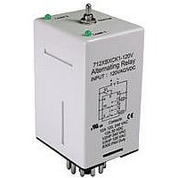
... Alternating Relays MCY98 Series Designed for duplex pumping systems where it is desirable to equalize pump run time. The solid state alternating circuit drives an internal electromechanical relay. A continuous power source and control switch are required. The control switch (Float, pressure or other isolated contact) is connected between the L1 terminal and the control terminal. Each time the control switch is opened the output contacts will change status, Indicator lights on the case show the internal relay status ...
Page 2
... Alternating Relays MCY98 Series General Specifications Contact Characteristics Contact Materials Thermal (Carrying Current) Maximum Switching Voltage Current Rating Switching Voltage Minimum Switching Requirement Coil Characteristics Operating Rage Average Consumption Drop-out Voltage Threshold Timing Characteristics Time delay - Fixed Reset Time Alternating Action ...
Page 3
... Fixed Page <3> Contact Rated Load Part Number Current SPDT 12 Amperes MCY98-57-120A DPDT 12 Amperes MCY98-53-120A DPDT 12 Amperes MCY98-54-120A DPDT 12 Amperes MCY98-55-120A V is Input Voltage LA is Load # Load # Control Switch # Input Voltage LA is Load # Load # Control Switch # Control Switch #2 04/08/11 V1.1 ...
Page 4
... Alternating Relays MCY98 Series Operation Wiring Diagram : MCY98-54 11 Pin Octal with a DPDT Contact Configuration. Pin 9 is Normally Closed and Pin 11 is Normally Open. If the top toggle switch is in “ Alternate” position closing switch S1 will alternate the loads between LA and LB. ...