EA-QSB-012 Embedded Artists, EA-QSB-012 Datasheet - Page 21
EA-QSB-012
Manufacturer Part Number
EA-QSB-012
Description
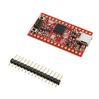
BOARD QUICK START LPC1343
Manufacturer
Embedded Artists
Specifications of EA-QSB-012
Lead Free Status / Rohs Status
Lead free / RoHS Compliant


NXP Semiconductors
LPC1311_13_42_43
Product data sheet
7.12.1 Features
7.13.1 Features
7.14.1 Features
7.13 10-bit ADC
7.14 General purpose external event counter/timers
The LPC1311/13/42/43 contains one ADC. It is a single 10-bit successive approximation
ADC with eight channels.
The LPC1311/13/42/43 includes two 32-bit counter/timers and two 16-bit counter/timers.
The counter/timer is designed to count cycles of the system derived clock. It can optionally
generate interrupts or perform other actions at specified timer values, based on four
match registers. Each counter/timer also includes one capture input to trap the timer value
when an input signal transitions, optionally generating an interrupt.
•
•
•
•
•
•
•
•
•
•
•
•
•
•
•
•
•
•
•
•
•
The I
pins. The I
Easy to configure as master, slave, or master/slave.
Programmable clocks allow versatile rate control.
Bidirectional data transfer between masters and slaves.
Multi-master bus (no central master).
Arbitration between simultaneously transmitting masters without corruption of serial
data on the bus.
Serial clock synchronization allows devices with different bit rates to communicate via
one serial bus.
Serial clock synchronization can be used as a handshake mechanism to suspend and
resume serial transfer.
The I
The I
10-bit successive approximation ADC.
Input multiplexing among 8 pins.
Power-down mode.
Measurement range 0 V to V
10-bit conversion time ≥ 2.44 μs (up to 400 kSamples/s).
Burst conversion mode for single or multiple inputs.
Optional conversion on transition of input pin or timer match signal.
Individual result registers for each ADC channel to reduce interrupt overhead.
A 32-bit/16-bit counter/timer with a programmable 32-bit/16-bit prescaler.
Counter or timer operation.
One capture channel per timer, that can take a snapshot of the timer value when an
input signal transitions. A capture event may also generate an interrupt.
2
2
2
C-bus interface is a standard I
C-bus can be used for test and diagnostic purposes.
C-bus controller supports multiple address recognition and a bus monitor mode.
2
C-bus interface also supports Fast-mode Plus with bit rates up to 1 Mbit/s.
All information provided in this document is subject to legal disclaimers.
Rev. 3 — 10 August 2010
DD
.
2
C-bus compliant interface with true open-drain
32-bit ARM Cortex-M3 microcontroller
LPC1311/13/42/43
© NXP B.V. 2010. All rights reserved.
21 of 62
Related parts for EA-QSB-012
Image
Part Number
Description
Manufacturer
Datasheet
Request
R

Part Number:
Description:
MCU, MPU & DSP Development Tools QUICKSTART PROTOTYPE BRD W/ LPC2129 CAN
Manufacturer:
Embedded Artists
Datasheet:

Part Number:
Description:
MCU, MPU & DSP Development Tools QUICKSTART PROTOTYPE BRD
Manufacturer:
Embedded Artists
Datasheet:

Part Number:
Description:
MCU, MPU & DSP Development Tools LPC2148 USB QUICKSTART BRD
Manufacturer:
Embedded Artists
Datasheet:

Part Number:
Description:
MCU, MPU & DSP Development Tools QUICKSTART PROTOTYPE BRD W/ LPC2106 RS232
Manufacturer:
Embedded Artists
Datasheet:
Part Number:
Description:
MCU, MPU & DSP Development Tools LPC2129 CAN QUICKSTART BRD
Manufacturer:
Embedded Artists
Datasheet:
Part Number:
Description:
MCU, MPU & DSP Development Tools QUICKSTART PROTOTYPE BRD W/ LPC2148
Manufacturer:
Embedded Artists
Datasheet:
Part Number:
Description:
MCU, MPU & DSP Development Tools LPC2106 RS232 QUICKSTART BRD
Manufacturer:
Embedded Artists
Datasheet:

Part Number:
Description:
Development Boards & Kits - ARM QUICK START BOARD LPC11U35
Manufacturer:
Embedded Artists
Datasheet:
Part Number:
Description:
KIT LPC3141 SODIMM 66X48 200POS
Manufacturer:
Embedded Artists
Datasheet:
Part Number:
Description:
KIT LPC3152 SODIMM 66X48 200POS
Manufacturer:
Embedded Artists
Datasheet:
Part Number:
Description:
BOARD OEM W/LPC2478 MCU
Manufacturer:
Embedded Artists
Datasheet:
Part Number:
Description:
KIT LPC3250 259 WITH QVGA
Manufacturer:
Embedded Artists
Datasheet: