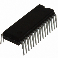
AN5870K Panasonic - SSG, AN5870K Datasheet - Page 13

AN5870K
Manufacturer Part Number
AN5870K
Description
IC SWITCH QUAD 2X1
Manufacturer
Panasonic - SSG
Datasheet
1.AN5870K.pdf
(16 pages)
Specifications of AN5870K
Function
Switch
Circuit
4 x 2:1
Voltage Supply Source
Single Supply
Voltage - Supply, Single/dual (±)
4.5 V ~ 5.25 V, 10.5 V ~ 12.6 V
Current - Supply
16mA
Operating Temperature
-20°C ~ 70°C
Mounting Type
Through Hole
Package / Case
30-SDIP (0.400", 10.16mm)
Lead Free Status / RoHS Status
Contains lead / RoHS non-compliant
Available stocks
Company
Part Number
Manufacturer
Quantity
Price
Part Number:
AN5870K
Manufacturer:
PANASONIC/松下
Quantity:
20 000
I Technical Information
When detecting
H. sync. signal
Operational explanation
1. SW block
2. High-level signal detection block
When rising
from 0 V
(Detection voltage change)
composite sync. signal (composite sync.) inside. H-in 1 and 2 pins (pin 13 or pin 14) are input
pins for the video signal and the separated horizontal signal.
selected in SW block and provides the output to H-out pin (pin 19) in the following manner.
inputted.
hysteresis characteristics. It is possible to adjust the H. sync. signal detection time by means of an
external capacitor.
When decreasing
from 5 V
Sync.-in pin (pin 21)
Switches over R, G, B, H, V signal of 2 systems.
SW pin (pin 22)
Sync.-in pin (pin 21) is a pin for inputting the sync.-on green signal and it is separated into the
The high-level signal detection block discriminates the presence of H-in signal which is
H signal detection pin (pin 20) voltage becomes under 1 V or over 4 V if H. sync. signal is not
The output signal for the H. sync. signal detection pin voltage becomes as follows and it has
(Sync.-in signal is selected
In high-level
when lowed under 1 V)
In low-level
G
G
(H-in signal is selected when lowed under 3 V)
0V
Sync-in signal selection
Input signal
(Detection voltage change)
R in 2 (Pin 3), G in 2 (pin 7), B in 2 (pin 11), H in 2 (pin 14), V in 2 (pin 16)
H-in pin (pin 13 · pin 14)
R in 1 (pin 1), G in 1 (pin 5), B in 1 (pin 9), H in 1 (pin 13), V in 1 (pin 15)
1V
1V
H-in signal selection
G
G
2V
SDB00035BEB
(H-in signal is selected if 2 V is exceeded)
2.5V
(Detection voltage change)
3V
DC (state of sync.-in pin)
H-out pin (pin 19)
Selected pins
H. sync. signal detection
pin voltage
Sync.-in signal selection
Sync.in signal
Output signal
H-in signal
H-in signal
4V
(Sync.-in signal is selected
when 4 V is exceeded)
(Detection voltage change)
5V
H. sync. signal
detection
pin voltage
H. sync. signal
detection
pin voltage
AN5870K
13


