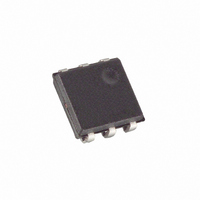
DS2409P/T&R Maxim Integrated Products, DS2409P/T&R Datasheet

DS2409P/T&R
Specifications of DS2409P/T&R
Related parts for DS2409P/T&R
DS2409P/T&R Summary of contents
Page 1
FEATURES § Low impedance coupler to create large common-ground, multi-level MicroLAN networks § Keeps inactive branches pulled high to 5V § Simplifies network topology analysis by logically decoupling devices on active network segments § Conditional search for fast-event signaling ...
Page 2
This significantly speeds up the analysis of topology and population in a continuously changing network. The coupler also supports the bus master in detecting arrivals on the inactive segments of the network by responding to the conditional search ...
Page 3
LASERED ROM Each DS2409 contains a unique ROM code that is 64 bits long. The first eight bits are a 1-Wire family code. The next 48 bits are a unique serial number. The last eight bits are a CRC ...
Page 4
CRC GENERATOR Figure 4 CONTROL FUNCTION COMMANDS The “Control Function Flow Chart” (Figure 5) describes the protocols necessary for controlling the main and auxiliary output as well as the control output of the DS2409. The 1-Wire Function Control section ...
Page 5
STATUS CONTROL BYTE Table DATA CNTR. X SEL. 0-2 X don’t care 3-4 Write control: both bits must change the status MODE control output mode selection auto-control mode (default), 1 ...
Page 6
DISCHARGE LINES [99h] There may be situations where one has to force a power-on reset for parasitically powered 1-Wire devices connected to the main or auxiliary output of the DS2409. For this purpose, the Discharge Lines command has been implemented. ...
Page 7
FUNCTION COMMAND FLOW CHART Figure ...
Page 8
FUNCTION COMMAND FLOW CHART Figure 5 (cont’ ...
Page 9
HARDWARE CONFIGURATION Figure 6 1-WIRE BUS SYSTEM The 1-Wire bus is a system which has a single bus master and one or more slaves. In all instances the DS2409 behaves as a slave. The discussion of this bus system is ...
Page 10
ROM FUNCTION COMMANDS Once the bus master has detected a presence, it can issue one of the five ROM function commands. All ROM function commands are eight bits long. A list of these commands follows (refer to flowchart in Figure ...
Page 11
ROM FUNCTIONS FLOW CHART Figure ...
Page 12
SIGNALING The DS2409 requires strict protocols to ensure data integrity. The protocol consists of four types of signaling on one line: Reset Sequence with Reset Pulse and Presence Pulse, Write 0, Write 1 and Read Data. All these signals ...
Page 13
READ/WRITE TIMING DIAGRAM Figure ...
Page 14
USAGE EXAMPLE Configuration: A bus master controls a MicroLAN consisting of a trunk with many DS2409s that create branches. Each of the DS2409s has a DS2430A connected to its auxiliary output to label its physical location in the network (see ...
Page 15
APPLICATION EXAMPLES Figures 10 and 11 show two application examples of the DS2409 MicroLAN Coupler. A single trunk with branches is the typical topology of an access control system with the iButtons being the electronic keys required for admittance. The ...
Page 16
DUAL MASTER SYSTEM Figure ...
Page 17
ABSOLUTE MAXIMUM RATINGS* Voltage on Data to Ground Operating Temperature Range Storage Temperature Range Soldering Temperature * This is a stress rating only and functional operation of the device at these or any other conditions above those indicated in the ...
Page 18
AC ELECTRICAL CHARACTERISTICS PARAMETER Time Slot Write 1 Low Time Write 0 Low Time Read Low Time Read Data Valid Release Time Read Data Setup Recovery Time Reset Time High Reset Time Low Presence Detect High Presence Detect Low NOTES: ...


