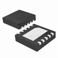
MAX1558ETB+T Maxim Integrated Products, MAX1558ETB+T Datasheet - Page 7

MAX1558ETB+T
Manufacturer Part Number
MAX1558ETB+T
Description
IC CURR-LIM SW DUAL PROG 10-TDFN
Manufacturer
Maxim Integrated Products
Datasheet
1.MAX1558ETBT.pdf
(14 pages)
Specifications of MAX1558ETB+T
Applications
USB
Interface
USB
Voltage - Supply
2.75 V ~ 5.5 V
Package / Case
10-TDFN Exposed Pad
Mounting Type
Surface Mount
Lead Free Status / RoHS Status
Lead free / RoHS Compliant
* ( ) are for the MAX1558H only.
The MAX1558/MAX1558H are dual current-limited
switches designed for USB applications. They have two
independent switches, each with its own enable control
input and autoreset function. Each switch has an error-
flag output to notify the USB controller when current-
limit, short-circuit, undervoltage-lockout, or thermal-
shutdown conditions occur (Figure 2). The MAX1558/
MAX1558H operate from a 2.7V to 5.5V supply. Each
output can supply up to 1.2A. Current limit for both
channels is set with one external resistor.
The MAX1558/MAX1558H have independent thermal
shutdown for each switch in the event of a prolonged
overload. An autoreset function monitors the output and
automatically turns the switch on when the overload is
removed. Separate current limiting and thermal-shut-
down circuits permit each switch to operate indepen-
dently, improving system robustness.
Dual, 3mm x 3mm, 1.2A/Programmable-Current
PIN
10
—
1
2
3
4
5
6
7
8
9
*(ONA)
*(ONB)
NAME
OUTB
OUTA
FLTB
FLTA
GND
ONA
ISET
ONB
PAD
INA
INB
_______________________________________________________________________________________
Detailed Description
Power Input for OUTA. Connect INA and INB together and bypass with a 0.1µF capacitor to ground.
Load conditions may require additional bulk capacitance to prevent the input from being pulled down.
Control Input for Switch A. Can be driven higher than IN_ without damage. A logic low turns switch A on
for the MAX1558. A logic high turns switch A on for the MAX1558H.
Current-Limit Adjust for Both Channels. Connect a resistor between 26kΩ to 60kΩ from ISET to ground to
program the current limit. See Setting the Current Limit in the Applications Information section.
Control Input for Switch B. Can be driven higher than IN_ without damage. A logic low turns switch B on
for the MAX1558. A logic high turns switch B on for the MAX1558H.
Power Input for OUTB. Connect INB and INA together and bypass with a 0.1µF capacitor to ground.
Load conditions may require additional bulk capacitance to prevent the input from being pulled down.
Power Output for Switch B. Connect a 1µF capacitor from OUTB to ground. The load condition may
require additional bulk capacitance.
Fault Indicator Output for Switch B. This open-drain output goes low when switch B is in thermal
shutdown or UVLO or in a sustained (>20ms) current-limit or short-circuit condition.
Ground
Fault Indicator Output for Switch A. This open-drain output goes low when switch A is in thermal
shutdown or UVLO or in a sustained (>20ms) current-limit or short-circuit condition.
Power Output for Switch A. Connect a 1µF capacitor from OUTA to ground. The load condition may
require additional bulk capacitance.
Exposed Pad, Internally Connected to GND. Connect exposed pad to a large copper trace for maximum
power dissipation.
USB Switches with Autoreset
Figure 1. Typical Application Circuit
2.7V TO 5.5V
FUNCTION
INPUT
0.1μF
100kΩ
100kΩ
*USB APPLICATIONS MAY REQUIRE ADDITIONAL
BULK CAPACITANCE
INA
INB
FLTA
FLTB
ISET
MAX1558
Pin Description
OUTA
OUTB
GND
ONA
ONB
1μF*
1μF*
ONA
ONB
USB
PORT A
USB
PORT B
7


