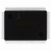
ISL54101ACQZ Intersil, ISL54101ACQZ Datasheet - Page 12

ISL54101ACQZ
Manufacturer Part Number
ISL54101ACQZ
Description
IC TMDS REGEN W/MUX 128-MQFP
Manufacturer
Intersil
Datasheet
1.ISL54101ACQZ.pdf
(21 pages)
Specifications of ISL54101ACQZ
Applications
Multimedia Displays, Test Equipment
Interface
I²C
Voltage - Supply
3 V ~ 3.6 V
Package / Case
128-MQFP, 128-PQFP
Mounting Type
Surface Mount
Lead Free Status / RoHS Status
Lead free / RoHS Compliant
Available stocks
Company
Part Number
Manufacturer
Quantity
Price
Register Listing
0x07
0x08
0x09
0x0A
0x0B
0x0C
0x10
ADDRESS
Equalization 1 (0xCC)
Equalization 2 (0xCC)
PRBS7 Error Counter Link 0 (read only)
PRBS7 Error Counter Link 1 (read only)
PRBS7 Error Counter Link 2 (read only)
PLL Bandwidth (0x10)
Recommended default: 0x12
Test Pattern Generator (0x00)
REGISTER (DEFAULT VALUE)
(Continued)
12
ISL54100A, ISL54101A, ISL54102A
BIT(S)
3:0
7:4
3:0
7:4
1:0
7:0
7:0
7:0
1:0
7:2
2
Channel A Equalizer
Gain
Channel B Equalizer
Gain
Channel C Equalizer
Gain
Channel D Equalizer
Gain
Generator Mode
Enable PRBS7 Error
Counter
PRBS7 Error
Counter Link 0
PRBS7 Error
Counter Link 1
PRBS7 Error
Counter Link 2
PLL Bandwidth
Reserved
FUNCTION NAME
Boost (dB) = 1dB + <gain value> * 0.8dB
0x0: 1dB boost at 800MHz
0xC: 10.6dB boost at 800MHz (default)
0xF: 13dB boost at 800MHz
Boost (dB) = 1dB + <gain value> * 0.8dB
0x0: 1dB boost at 800MHz
0xC: 10.6dB boost at 800MHz (default)
0xF: 13dB boost at 800MHz
When a 25MHz to 165MHz clock is applied to the selected
channel’s clock input, this function will output a PRBS7
pattern on the TX pins.
0: Normal operation (test patterns disabled)
1: PRBS7 pattern
2: Low frequency toggle (0000011111…)
3: High frequency toggle (1010101010…)
Note: When switching from the high frequency toggle
pattern to the low frequency toggle pattern, you must first
select normal operation.
Enables PRBS7 error counter in registers 0x0A to 0x0C.
0: Disable PRBS7 Error Counter
1: Enable PRBS7 Error Counter
PRBS7 Error Counter of Link 0. Saturates at 0xFF. Reading
this register clears this register at end of read
PRBS7 Error Counter of Link 1. Saturates at 0xFF. Reading
this register clears this register at end of read
PRBS7 Error Counter of Link 2. Saturates at 0xFF. Reading
this register clears this register at end of read
Selects between 4 PLL bandwidth settings
0: 4MHz (silicon default)
1: 2MHz
2: 1MHz (recommended default)
3: 500kHz
1MHz provides slightly better performance with high jitter/
high noise signals.
Keep set to 000100 binary.
DESCRIPTION
June 17, 2008
FN6725.0


