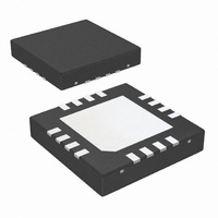
DS15EA101SQ/NOPB National Semiconductor, DS15EA101SQ/NOPB Datasheet - Page 3

DS15EA101SQ/NOPB
Manufacturer Part Number
DS15EA101SQ/NOPB
Description
IC EQUAL CBL ADAPT 1.5GBPS 16LLP
Manufacturer
National Semiconductor
Datasheet
1.DS15EA101SQNOPB.pdf
(12 pages)
Specifications of DS15EA101SQ/NOPB
Applications
Displays
Interface
Coax Cable and Female Connector
Voltage - Supply
3.135 V ~ 3.465 V
Package / Case
16-LLP
Mounting Type
Surface Mount
Ic Interface Type
Serial
Supply Voltage Range
3.135V To 3.465V
Power Dissipation Pd
210mW
Operating Temperature Range
-40°C To +85°C
Digital Ic Case Style
LLP
No. Of Pins
16
Rohs Compliant
Yes
Number Of Channels Per Chip
1
Supply Voltage (max)
3.6 V
Supply Voltage (min)
3 V
Maximum Operating Temperature
+ 85 C
Mounting Style
SMD/SMT
Operating Current
63 mA
Operating Voltage
3.3 V
Lead Free Status / RoHS Status
Lead free / RoHS Compliant
Other names
DS15EA101SQTR
Available stocks
Company
Part Number
Manufacturer
Quantity
Price
Company:
Part Number:
DS15EA101SQ/NOPB
Manufacturer:
ADI
Quantity:
988
Symbol Parameter
BR
t
tTLH
tTHL
R
TRJ
OUT
AC Electrical Characteristics
Over Supply Voltage and Operating Temperature ranges, unless otherwise specified (Note 3).
Note 1: "Absolute Maximum Ratings" are those parameter values beyond which the life and operation of the device cannot be guaranteed. The stating herein of
these maximums shall not be construed to imply that the device can or should be operated at or beyond these values. The table of "Electrical Characteristics"
specifies acceptable device operating conditions.
Note 2: Current flow into device pins is defined as positive. Current flow out of device pins is defined as negative. All voltages are stated referenced to 0 volts.
Note 3: Typical values are stated for V
Note 4: Specification is guaranteed by characterization.
Note 5: Specification is guaranteed by design.
Note 6: The maximum input voltage amplitude assumes a DC-balanced signal.
Note 7: Supply current depends on the amount of cable being equalized. The current is highest for short cable and decreases as the cable length is increased.
Note 8: The total residual jitter at BER-12 was calculated as DJ+14.1xRJ, where DJ is deterministic jitter and RJ is random jitter. The jitter is expressed as a
portion of a unit interval (UI). One UI is a reciprocal of a bit rate (or data rate). For example, a 1.5 Gbps (gigabit per second) signal has 1 / (1.5 Gb/s) = 666.67
ps (picosecond) unit interval. A 0.25 UI jitter is equivalent to 0.25 x 666.67 ps = 166.67 ps.
IN
Input Data Rate
Total Residual Jitter @ BER-12
(Note 8)
Transition Time from Low to High 20% – 80%, (Note 4)
Transition Time from High to Low 20% – 80%, (Note 4)
Output Resistance
CC
= +3.3V and T
Conditions
1.5 Gbps
25m CAT5e (Belden 1700A),
(Note 3)
1.0 Gbps
50m CAT5e (Belden 1700A),
(Note 3)
0.5 Gbps
100m CAT5e (Belden 1700A),
(Note 3)
1.5 Gbps
50m CAT7 (Siemon Tera),
(Note 3)
1.5 Gbps
75m CAT7 (Siemon Tera),
(Note 3)
1.0 Gbps
100m CAT7 (Siemon Tera),
(Note 3)
1.5 Gbps
200m Belden 9914,
(Note 3)
single-ended, (Note 5)
A
= +25°C.
3
Reference
IN+, IN-
OUT+, OUT-
Min
150
0.25
0.25
0.25
0.25
0.30
0.40
0.25
Typ
100
100
50
1500
Max
220
220
www.national.com
Units
Mbps
ps
ps
UI
UI
UI
UI
UI
UI
UI
Ω


